Waste heat recovery device for coating environmental-friendly mechanical equipment

A technology of waste heat recovery device and mechanical equipment, applied in lighting and heating equipment, steam generation method using heat carrier, dispersed particle filtration, etc., can solve the problems affecting waste heat recovery, environmental pollution, inconvenient connection, etc. The effect of eliminating irritating odor and easy replacement

Inactive Publication Date: 2019-01-04
海数(青岛)医学科技有限公司
View PDF0 Cites 3 Cited by
  • Summary
  • Abstract
  • Description
  • Claims
  • Application Information

AI Technical Summary

Problems solved by technology

[0003] However, in the use of the current waste heat recovery device for coating environmental protection machinery and equipment, it is found that due to the difference in height with the connected drying device, when the same waste heat recovery device is connected to a different structure type of drying device, it will cause The connection is inconvenient, which affects the recovery of waste heat. In addition, the heat recovered from waste heat generally contains the pungent smell carried by the coating machine. After the waste heat is recovered, the pungent smell will not disappear, so direct discharge will also cause pollution to the environment

Method used


Image

  • Waste heat recovery device for coating environmental-friendly mechanical equipment
  • Waste heat recovery device for coating environmental-friendly mechanical equipment
  • Waste heat recovery device for coating environmental-friendly mechanical equipment

Examples


Embodiment Construction

[0020] The following will clearly and completely describe the technical solutions in the embodiments of the present invention with reference to the accompanying drawings in the embodiments of the present invention. Obviously, the described embodiments are only some, not all, embodiments of the present invention. Based on the embodiments of the present invention, all other embodiments obtained by persons of ordinary skill in the art without making creative efforts belong to the protection scope of the present invention.

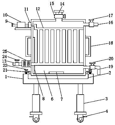
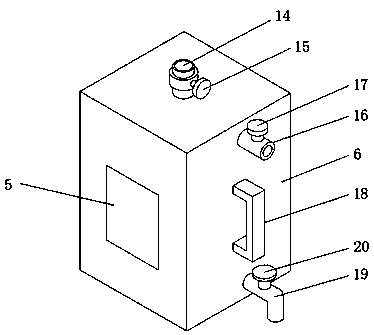
[0021] The present invention provides such Figure 1-5 The waste heat recovery device for coating environmental protection mechanical equipment shown includes a base 1, a turntable 2 and a water tank 6. The turntable 2 is embedded in the upper end surface of the base 1 and is connected to the base 1 through a rotating shaft in rotation. The four corners of the bottom end surface of the base 1 are equipped with vertical telescopic legs 3, the telescopic legs 3 ...


PUM


Abstract

The invention discloses a waste heat recovery device for coating environmental-friendly mechanical equipment. The waste heat recovery device comprises a base, a rotating disc and a water tank. The rotating disc is internally embedded in the upper end face of the base, and rotatably connected with the base through a built-in rotating shaft. Vertical telescopic supporting legs are installed at the four corners of the bottom end face of the base correspondingly, the telescopic supporting legs are electric telescopic rods, the water tank is fixed to the rotating disc, and the bottom end of the water tank is internally embedded in the rotating disc. Pushing rods with U-shaped structures are installed on the two symmetrical side faces of the water tank correspondingly, an air inlet pipe is arranged at the top end of the side face where one group of pushing rods are located, and an air outlet pipe is arranged at the near-bottom end of the side face where the group of pushing rods are located,the air inlet pipe extends into the water tank and is connected with a top end interface of a heat conduction pipe inside the water tank, and an extraction fan and an air pump are further connected to the position, on the exterior of the water tank, of the air inlet pipe. According to the waste heat recovery device for the coating environmental-friendly mechanical equipment, connection and fixation with a drying device are convenient, hot air in the drying device is subjected to waste heat recovery advantageously, and pollution of exhaust gas to the environment is reduced.

Description

technical field [0001] The invention belongs to the technical field of coating environmental protection mechanical equipment, and in particular relates to a waste heat recovery device of coating environmental protection mechanical equipment. Background technique [0002] As we all know, the waste heat recovery device of coating environmental protection machinery and equipment is a device that recovers the heat generated during the drying process of coating equipment to achieve environmental protection and high efficiency. It is widely used in the field of coating environmental protection; During the use of the existing waste heat recovery device for environmental protection coating machinery and equipment, the device needs to be moved to the drying device side of the environmental protection coating mechanical equipment, so that the air intake pipe of the waste heat recovery device is connected with the drying device, thereby Realize waste heat recovery treatment of coating ...

Claims


Application Information

Patent Timeline
Patent Type & Authority Applications(China)
IPC IPC(8): F22B1/18F22B35/00B01D46/00B01D46/30B01D53/04
CPCF22B1/1884B01D46/0035B01D46/30B01D53/04B01D2253/102F22B35/007
Inventor 蔡腾
Owner 海数(青岛)医学科技有限公司
Why Eureka
Try Eureka