Mini combustor

A micro combustion and combustion chamber technology, applied in the field of construction machinery, can solve the problems of large size, low integration, and inconvenient movement of the burner, and achieve the effects of small size, increased atomization area, and fast ignition speed

Inactive Publication Date: 2019-01-04
北京美寒机械设备有限公司
View PDF4 Cites 0 Cited by
  • Summary
  • Abstract
  • Description
  • Claims
  • Application Information

AI Technical Summary

Problems solved by technology

[0004] The invention designs a micro burner, which solves the technical problems aimed at the disadvantag

Method used


Image

  • Mini combustor
  • Mini combustor
  • Mini combustor

Examples


Embodiment Construction

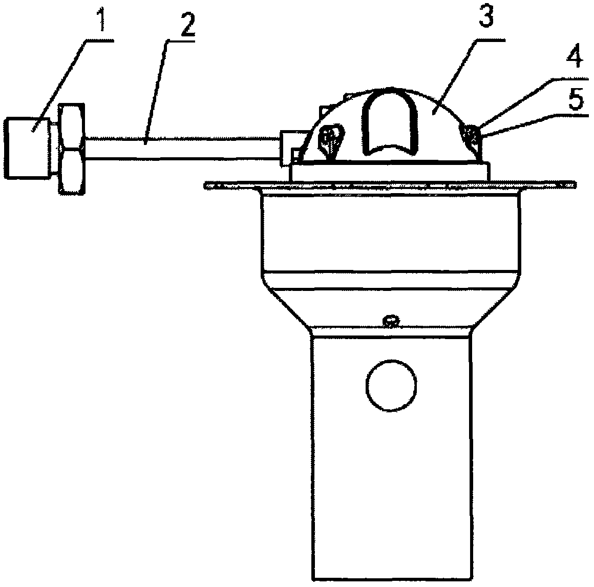
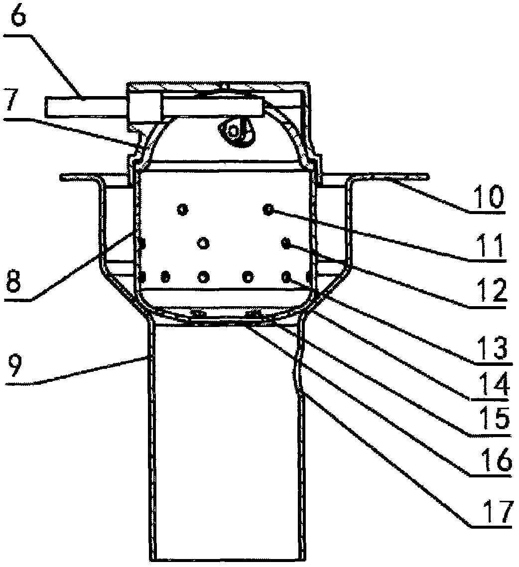
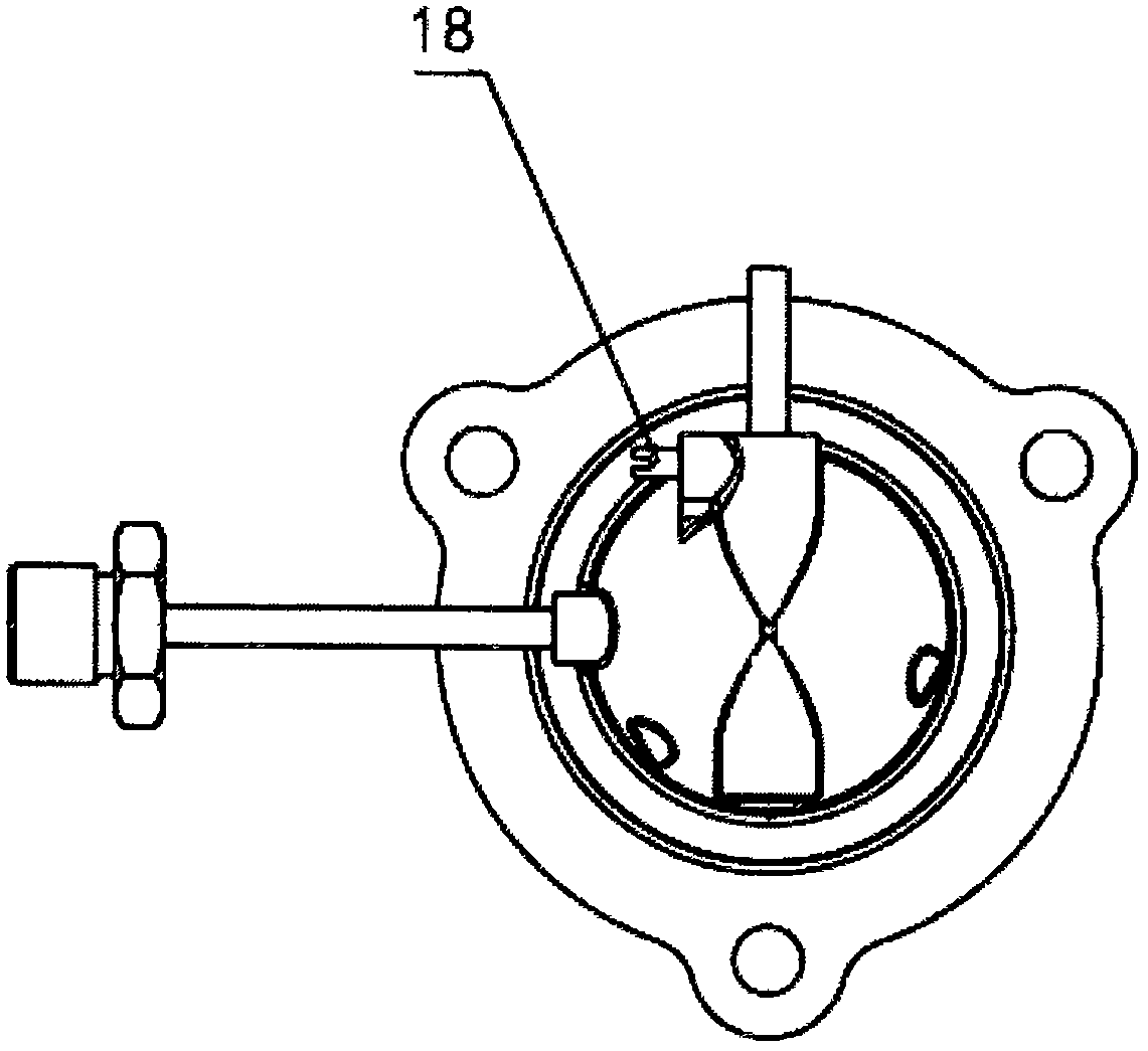
[0023] Combine below Figure 1 to Figure 3 , the present invention is further described:

[0024] A miniature atomizer for fuel atomization, ignition and combustion, including a fuel pipe rotary joint 1, an oil inlet pipe 2, an atomization cover 3, a protrusion 4, an air duct hole 5, a glow plug 6, an atomization net 7, a wind Cover 8, flame nozzle 9, mounting flange 10, first air inlet hole 11, second air inlet hole 12, third air inlet hole 13, welding hole 14, small gas outlet hole 15, large Gas outlet hole 16, flame detection hole 17 and set screw 18.

[0025] The oil pipe rotary joint 1 is used to connect the external fuel pipe, and the fuel is introduced into the oil inlet pipe 2. The oil inlet pipe 2 is made of seamless stainless steel pipe, and the inner diameter of the pipe cannot exceed 3mm. The cover 3 is welded together by welding. The fuel flows into the atomizing cap 3 through the oil pipe rotary joint 1 and the oil inlet pipe 2 . The atomizing net 7 is placed...


PUM

PropertyMeasurementUnit
Apertureaaaaaaaaaa
Diameteraaaaaaaaaa
Diameteraaaaaaaaaa

Abstract

The invention relates to a mini combustor. The mini combustor is characterized by comprising an atomizing cover (3), an atomizing net (7), an air cover (8) and a flame jetting pipe (9), wherein the atomizing net (7) is mounted in the atomizing cover (3); an opening in the lower part of the atomizing cover (3) is connected to an opening in the upper part of the air cover (8) to form a mini combustion chamber body; an outlet in the lower part of the air cover (8) is connected to the flame jetting pipe (9); fuel oil enters the combustion chamber body from the atomizing cover (3) through an oil inlet pipe (2); and a plurality of duct holes (5) are designed in the atomizing cover (3). The mini combustor has the advantages of being small in size, light in weight, low in energy consumption, fastto ignite, high in combustion stability, low in igniting environment temperature and the like; and the mini combustor is applicable to an outdoor furnace, a cooling liquid heating device, a low-temperature starting device of a diesel engine, etc.

Description

technical field [0001] The design of the invention belongs to the technical field of engineering machinery, and specifically relates to a micro burner which uses various liquid fuels such as diesel oil, kerosene, biodiesel and alcohol as fuel, and integrates fuel atomization and ignition. Background technique [0002] The burner is a device that atomizes a certain amount of fuel and mixes it with air in a certain proportion to form a combustible mixture, burns after ignition, and sprays out a high-temperature flame. Large-scale burners are widely used in boilers, furnaces, smelting furnaces, road construction machinery and heat treatment industries. The heating power of the fuel atomization and ignition devices is more than 100 kilowatts, and the 220V or 380V AC voltage is used. The internal structure is complex, including Complex air supply, fuel supply, fuel atomization nozzles, etc., are heavy and generally move in fixed or small-scale places. Small burners are used for ...

Claims


Application Information

Patent Timeline
IPC IPC(8): F23D11/00F23D11/36
CPCF23D11/00F23D11/36
Inventor 余小红吉雪龙刘计平
Owner 北京美寒机械设备有限公司
Why Eureka
Try Eureka