
Capacitive voltage divider vacuum drying system and method for mutual inductor

A capacitive voltage divider and vacuum drying technology, which is applied in the direction of drying solid materials, drying solid materials without heating, drying, etc., can solve the problems of high energy consumption, large dispersion of drying effect, long processing time, etc.

Active Publication Date: 2019-01-04
山东泰开互感器有限公司
View PDF6 Cites 3 Cited by
  • Summary
  • Abstract
  • Description
  • Claims
  • Application Information

AI Technical Summary

Problems solved by technology

[0003] After the capacitive voltage divider is manufactured, it needs to have a certain insulation performance. Usually, the completed capacitive voltage divider is dried. At present, the drying of the capacitive voltage divider is mainly processed by the overall drying and impregnation process. These processes are all The existence of insulating oil is unfavorable to the occupational health and safety of operators and the external environment; the drying efficiency is not high, the energy consumption is high, the processing time is long, and the overall drying effect is highly dispersed; the temperature resistance requirements of the capacitor voltage divider components are Increased capacitive divider material cost

Method used


Image

  • Capacitive voltage divider vacuum drying system and method for mutual inductor
  • Capacitive voltage divider vacuum drying system and method for mutual inductor
  • Capacitive voltage divider vacuum drying system and method for mutual inductor

Examples


Embodiment Construction

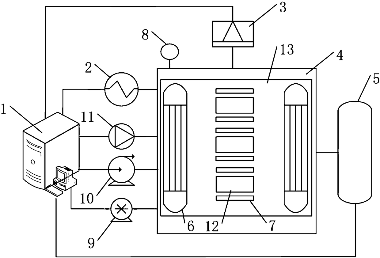
[0067] The present invention provides a capacitive voltage divider vacuum drying system for transformers, such as figure 1 As shown, it includes: a controller 1, a dehumidifier 3, a drying device 4, a heating mechanism, a drying position 12 and a vacuum device;

[0068] The drying device 4 is provided with a drying space 13 inside; the heating mechanism, the dehumidifier 3, and the vacuum device are respectively connected to the drying space 13 of the drying device; the drying space 13 is provided with a drying place 12 inside which is placed on the drying place 12 to be dried The capacitor divider; a break valve is provided between the dehumidifier 3 and the drying space 13; the drying space 13 of the drying device 4 is provided with a temperature sensor 7 for sensing the temperature of the drying space 13 and a pressure sensor 8 for sensing the pressure of the drying space 13 The vacuuming device is used to vacuum the drying space 13 of the drying device 4; the heating mechanism...


PUM


Abstract

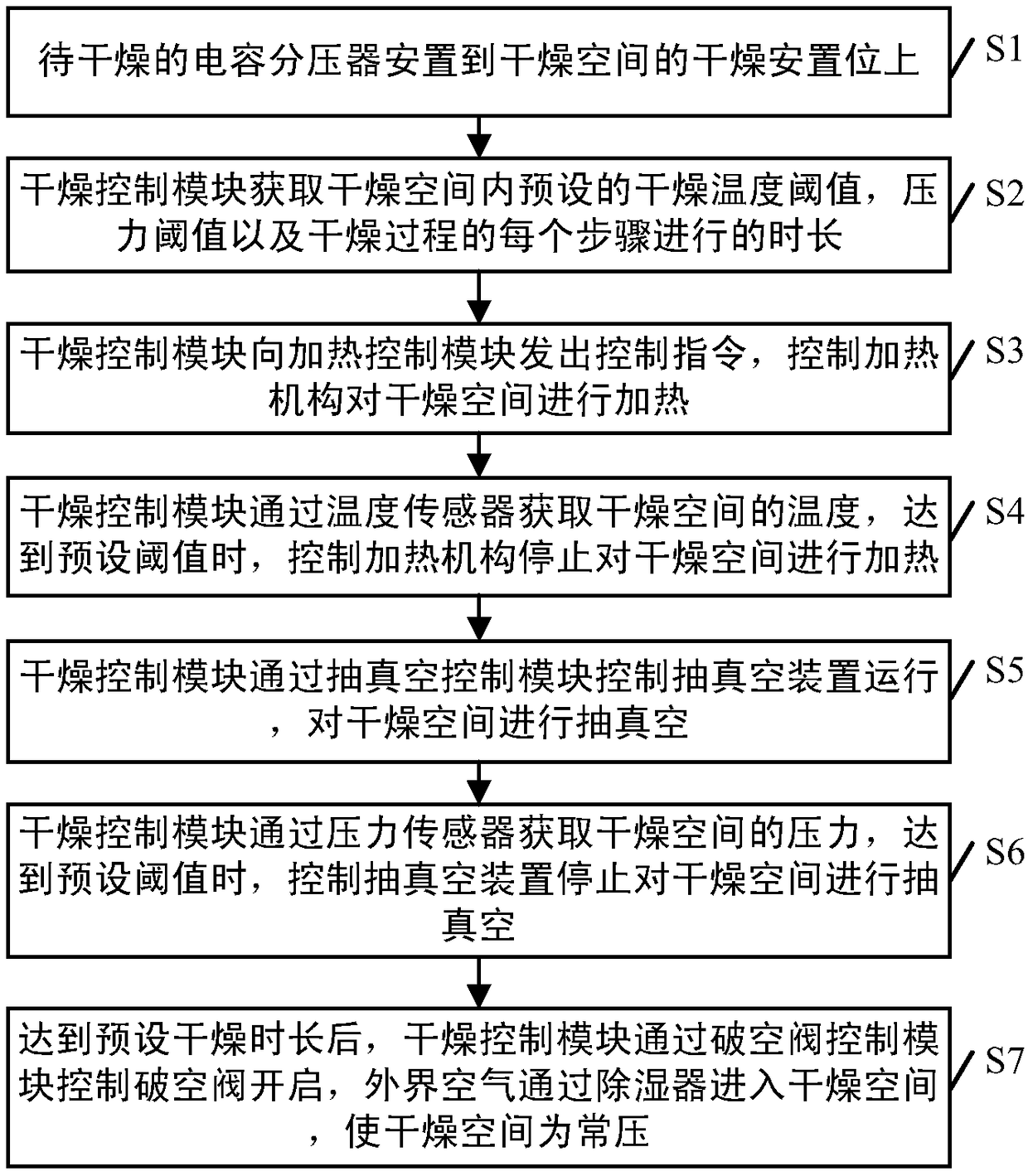
The invention provides a capacitive voltage divider vacuum drying system and method for a mutual inductor. A capacitive voltage divider to be dried is placed at a dry placement position of a drying space; a drying control module obtains a preset drying temperature threshold value, a pressure threshold value and duration of each step in the drying process in the drying space; a heating mechanism heats the drying space; a vacuum pumping device performs vacuum pumping on the drying space; after the preset drying duration is reached, the drying control module controls the opening of a vacuum breaker valve through a vacuum breaker valve control module, and the outside air enters the drying space through a dehumidifier, so that the drying space is atmospheric pressure. The presence or absence ofdew drops is observed by an observation mirror to determine the drying condition of the capacitive voltage divider. The entire drying process is free of insulating oil, and people and the environmentare not affected; and the drying rate is high, the product treatment effect is good, the temperature of the product drying process is easy to control, and the internal insulation damage of products is not caused.

Description

Technical field [0001] The invention relates to the technical field of transformer manufacturing, in particular to a vacuum drying system and method for a capacitive voltage divider for a transformer. Background technique [0002] Capacitor voltage divider is generally used to measure AC high voltage. Compared with ordinary resistive voltage divider, it has higher pressure resistance and is not easy to break down. The capacitive voltage divider is used to measure the impulse voltage. The capacitive voltage divider is also used in the high-voltage AC withstand voltage test to perform series resonance and resonate with the reactor. [0003] After the capacitor voltage divider is manufactured, it needs to have certain insulation properties. The finished capacitor voltage divider is usually dried. At present, the capacitor voltage divider is mainly dried by the overall drying dipping method. These processes are all processed in the process. The existence of insulating oil is detrimen...

Claims


Application Information

Patent Timeline
Patent Type & Authority Applications(China)
IPC IPC(8): F26B5/04F26B23/10F26B25/00
CPCF26B5/04F26B23/10F26B25/00
Inventor 韩斐吴光斌王世宝
Owner 山东泰开互感器有限公司
Learn More