
Method for preparing resistive gas electron multiplier film and resistive gas electron multiplier film
A technology of gas electron multiplication and thin film, applied in the direction of instruments, circuits, discharge tubes, etc., can solve the problems of loss of resistive electrodes, low gain, no signal, etc., and achieve the effect of stable performance, excellent performance and low cost
- Summary
- Abstract
- Description
- Claims
- Application Information
AI Technical Summary
Problems solved by technology
Method used
Image


Examples
Embodiment
[0067] GEM films were prepared by the following steps:
[0068] Step 1. Use Teer 650 magnetron sputtering equipment to deposit DLC with a thickness of 100nm on both the upper and lower surfaces of the APICAL substrate with a thickness of 50μm and a size of 15cm×15cm. The surface resistivity of DLC is about 50MΩ / □. Then plate copper with a thickness of 4.3 μm on the surface of the DLC;
[0069] Step 2. Within the range of 10cm×10cm in the central area of the substrate obtained in step 1, use wet etching to etch the copper layer on the upper and lower surfaces of the substrate with a diameter of 70 μm and a pitch of 140 μm, arranged in a hexagonal array holes, so that the DLC under the copper layer is exposed in the area of the hole array.
[0070] Step 3, taking the substrate obtained in step 2 out of the copper etching solution, washing it with water, and then putting it in an oven at 70°C for 2 hours to dry;
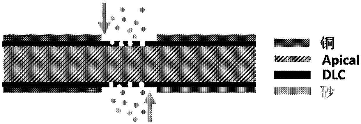
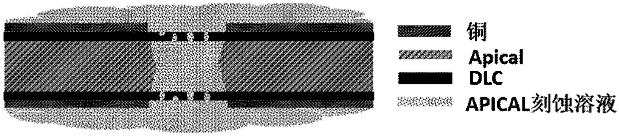
[0071] Step 4. Sandblasting the upper and lower surfaces of ...
PUM
| Property | Measurement | Unit |
|---|---|---|
| thickness | aaaaa | aaaaa |
| thickness | aaaaa | aaaaa |
| thickness | aaaaa | aaaaa |
Abstract
Description
Claims
Application Information