
A microchannel heat sink with hybrid structure

A hybrid structure, micro-channel technology, applied in laser parts, laser cooling devices, laser parts and other directions, can solve the problems of large pressure loss ΔP, high pressure loss, limited heat flux density q, etc., to improve temperature uniformity, The effect of increasing the flow space and reducing the pressure loss

Active Publication Date: 2019-01-04
TSINGHUA UNIV
View PDF10 Cites 10 Cited by
  • Summary
  • Abstract
  • Description
  • Claims
  • Application Information

AI Technical Summary

Problems solved by technology

In 1981, two scholars in the United States proposed the concept of microchannel liquid cooling. They used a microchannel array heat sink with a width of 50 μm and a height of 320 μm to achieve 790W / cm 2 High heat flux density cooling requirements, but the required pressure loss is as high as 216kPa, it is difficult to obtain practical application
[0004] For this reason, a large number of scholars have improved and optimized the structure of the micro-channel heat sink, but the problems existing in the current micro-channel heat sink are: 1. If you want to achieve a larger heat flux q, the pressure loss ΔP that needs to be paid will be larger Very large; 2. Reasonable pressure loss ΔP, the heat flux q that can be dissipated is very limited; 3. The heat dissipation of the micro-channel heat sink brings the unevenness of the chip temperature, which brings thermal stress and affects the reliability of the chip , performance, and life are adversely affected

Method used


Image

  • A microchannel heat sink with hybrid structure
  • A microchannel heat sink with hybrid structure
  • A microchannel heat sink with hybrid structure

Examples


Embodiment Construction

[0027] The following will clearly and completely describe the technical solutions in the embodiments of the present invention with reference to the accompanying drawings in the embodiments of the present invention. Obviously, the described embodiments are only some, not all, embodiments of the present invention. Based on the embodiments of the present invention, all other embodiments obtained by persons of ordinary skill in the art without making creative efforts belong to the protection scope of the present invention.

[0028] The purpose of the present invention is to provide a micro-channel heat sink with a hybrid structure to solve the problems existing in the prior art, which can simultaneously enhance heat transfer and reduce pressure loss, and improve the uniformity of chip surface temperature, thereby improving the reliability of the chip performance, performance and longevity.

[0029] In order to make the above objects, features and advantages of the present inventio...


PUM


Abstract

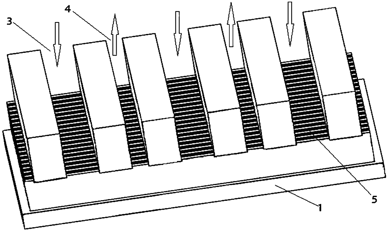
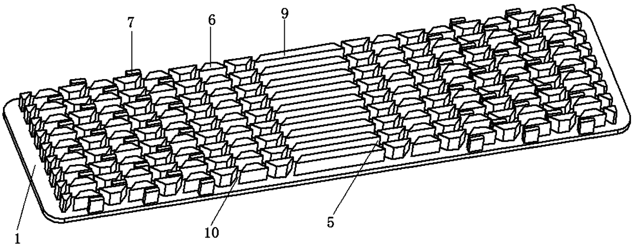
A microchannel heat sink with hybrid structure comprises a heat sink module and a cover plate which are sealingly connected, the cover plate is located above the heat sink module, the cover plate is provided with a plurality of spaced inlets and outlets, A heat sink module includes a substrate and a microchannel heat dissipation structure obtained on the substrate by etching or machining, The micro-channel heat dissipation structure comprises a plurality of fins arranged in parallel, wherein the fins form a micro-channel, the micro-channel is arranged vertically with an inlet and an outlet, asecondary flow channel is arranged on the fins, and a rectangular fin is arranged between the inlet and the outlet; A large rib corresponding to the inlet is arranged on the base below the inlet, andthe length of the large rib is equal to the width of the inlet. The mixed structure heat sink composed of the manifold type, the secondary flow channel and the rectangular fin shortens the flow distance of the coolant in the microchannel, increases the flow space, and enhances the disturbance in the flow process, thereby simultaneously enhancing heat exchange and reducing pressure loss, and further improving the uniformity of the chip temperature.

Description

technical field [0001] The invention relates to the technical field of heat sinks, in particular to a microchannel heat sink with a mixed structure. Background technique [0002] With the advancement of science and technology, the computing speed of the chip is getting faster and higher, and the integration is getting higher and higher, so more and more heat is generated per unit area. If the heat cannot be taken away in time, the reliability of the chip will be reduced. , the performance will decrease and the life will be shortened. [0003] One of the ways to solve this problem is to take the heat away through the heat sink structure, including air cooling and liquid cooling. Air cooling is suitable for heat flux density less than 10W / cm 2 In some cases, for high heat flux dissipation requirements, it is necessary to introduce liquid for cooling. In 1981, two scholars in the United States proposed the concept of microchannel liquid cooling. They used a microchannel arra...

Claims


Application Information

Patent Timeline
IPC IPC(8): H01S3/04H01S5/024
CPCH01S3/0407H01S5/02423
Inventor 曹炳阳杨敏
Owner TSINGHUA UNIV
Learn More