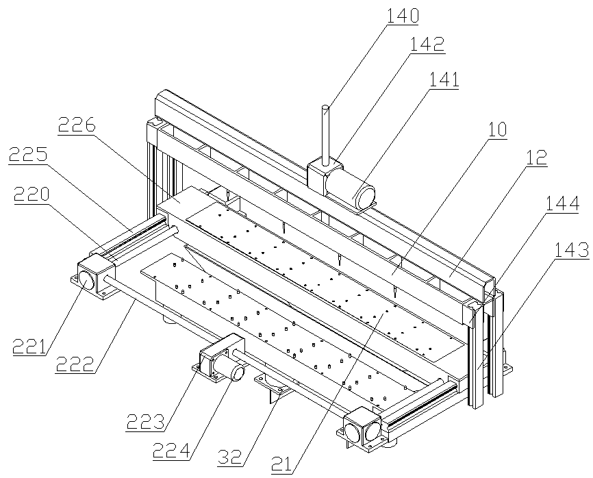
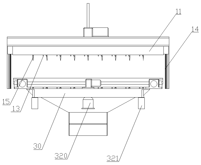
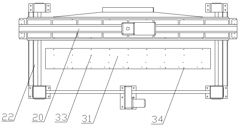
Automatic graphite boat sticking point exchanging machine die

A graphite boat and replacement machine technology, which is applied in the direction of gaseous chemical plating, coating, electrical components, etc., can solve problems such as shedding, complicated and cumbersome operations by personnel, and damage to stuck points

Pending Publication Date: 2019-01-08
江苏润阳悦达光伏科技有限公司
View PDF8 Cites 7 Cited by
  • Summary
  • Abstract
  • Description
  • Claims
  • Application Information

AI Technical Summary

Problems solved by technology

[0003] The replacement method of the traditional graphite boat sticking point is complicated and cumbersome, and at the same time requires relatively high skills for the assembler. If the skill is not in place, the graphite boat sheet and the graphite boat stuck point will be damaged or the assembly will not be in place during the replacement process. The traditional graphite boat The operation method for replacing the stuck point of the boat is: the stuck point of the graphite boat needs to use a simple manual press, and at the same time, the two sides of the press need to be padded with foam boards or rubber leather pads to the same height as the manual press platform, and the operator sits on the press. Place the graphite boat flat on the manual press platform in front of the machine, and then remove the 24 sticking points of the graphite boat with a manual press in turn. After the graphite boat sticking points are removed, the operator will replace the new st...

Method used


Image

  • Automatic graphite boat sticking point exchanging machine die
  • Automatic graphite boat sticking point exchanging machine die
  • Automatic graphite boat sticking point exchanging machine die

Examples


Embodiment Construction

[0021] The following description serves to disclose the present invention to enable those skilled in the art to carry out the present invention. The preferred embodiments described below are only examples, and those skilled in the art can devise other obvious variations. The basic principles of the present invention defined in the following description can be applied to other embodiments, variations, improvements, equivalents and other technical solutions without departing from the spirit and scope of the present invention.

[0022] In the description of the present invention, it should be noted that the orientation or positional relationship indicated by the terms "upper", "lower", "left", "right", etc. is based on the orientation or positional relationship shown in the drawings, and is only for It is convenient to describe the present invention and simplify the description, but does not indicate or imply that the device or element referred to must have a specific orientation...


PUM


Abstract

The invention belongs to the field of manufacturing of solar batteries, and particularly relates to an automatic graphite boat sticking point exchanging machine die. The automatic graphite boat sticking point exchanging machine die comprises an upper die assembly, a middle die assembly and a lower die assembly, when the automatic graphite boat sticking point exchanging machine die is used, a graphite boat of which sticking points need exchanging is placed in a graphite boat carrying platform in the middle die assembly, old sticking points are unloaded by the upper die assembly through utilizing upper die point unloading columns on the upper die assembly, then the middle die assembly is subjected to displacement to a point loading position, and the lower die assembly is also lifted and is subjected to displacement to the point loading position at the same time; new sticking points are mounted on the graphite boat through a point loading machine; the lower die assembly is used for achieving the effects of supporting and positioning in the course of loading the sticking points. The automatic graphite boat sticking point exchanging machine die disclosed by the invention is high in automation degree, easy and simple to operate, high in working efficiency and exchanging quality, and free from damaging the sticking points; the qualified rate of products is increased, the labor intensity of operators is alleviated, the working space and working environment are improved, and the application prospect is wide.

Description

technical field [0001] The invention belongs to the field of solar cell manufacturing, and in particular relates to an automatic graphite boat stick point replacement machine mold. Background technique [0002] With the rapid development of solar cells, more and more solar cells have entered the civilian field. In the production process of solar cells, PECVD (Plasma Enhanced Chemical Vapor Deposition, plasma enhanced chemical vapor deposition method) coating process is an important link in the production process and plays a pivotal role. PECVD uses microwave or radio frequency to ionize the gas containing the constituent atoms of the film to form plasma locally, and the plasma is highly chemically active and easy to react, depositing the desired film on the substrate. When the silicon wafer is subjected to its surface coating process, it is necessary to insert the uncoated silicon wafer into the carrier of the PECVD vacuum coating equipment. At present, the wafer carrier u...

Claims


Application Information

Patent Timeline
IPC IPC(8): C23C16/458H01L31/18
CPCH01L31/18C23C16/458Y02P70/50
Inventor 孙红彬段波唐福云卢佩良李宁高顺高东坡王银王志清蔡振华王枫
Owner 江苏润阳悦达光伏科技有限公司
Why Eureka
Try Eureka