
Radial shearing interferometer based on cosine wave strap piece

A shear interferometer and cosine wave technology, applied in the field of optical information measurement, can solve the problems of inconvenience and complex structure of radial shear interferometer, and achieve the effect of expanding the application field, simple structure and simplified structure

Active Publication Date: 2019-01-08
INST OF OPTICS & ELECTRONICS - CHINESE ACAD OF SCI
View PDF4 Cites 6 Cited by
  • Summary
  • Abstract
  • Description
  • Claims
  • Application Information

AI Technical Summary

Problems solved by technology

[0005] The technical problems to be solved by the present invention are: 1. The traditional radial shearing interferometer has a complex structure, requires multiple optical elements to realize radial shearing interference, and is inconvenient to adjust

Method used


Image

  • Radial shearing interferometer based on cosine wave strap piece
  • Radial shearing interferometer based on cosine wave strap piece
  • Radial shearing interferometer based on cosine wave strap piece

Examples


Embodiment Construction

[0029] The present invention will be further described below in conjunction with drawings and embodiments.

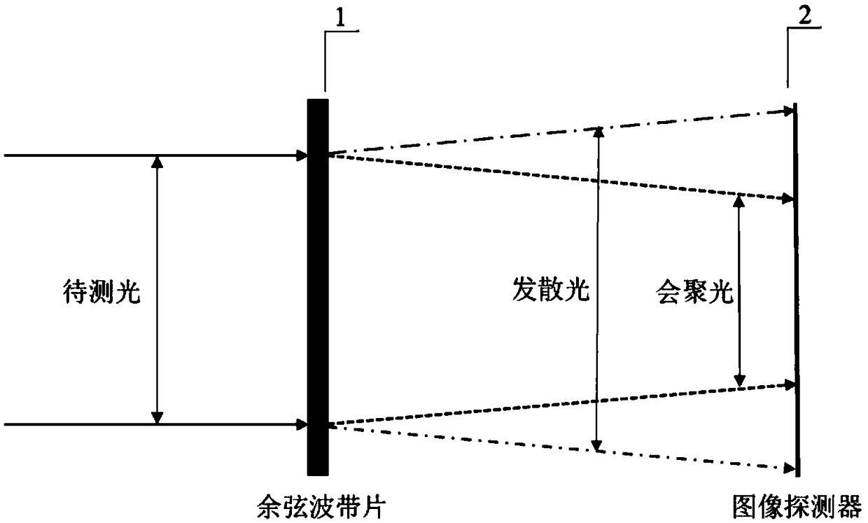
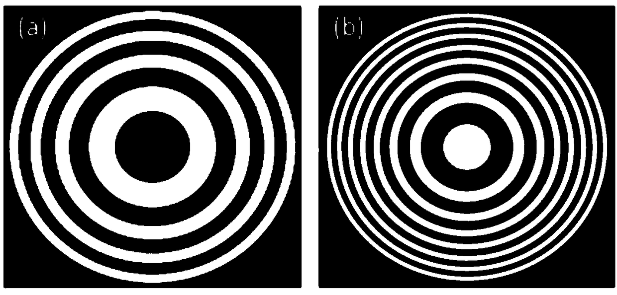
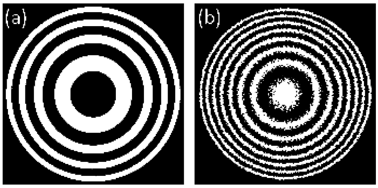
[0030] like figure 1 As shown, the radial shear interferometer based on the cosine wave zone plate in the embodiment of the present invention is composed of a cosine wave zone plate 1 and a CCD imaging detector 2, as figure 2 As shown, the complex amplitude transmittance of an ideal cosine wave zone plate changes continuously from -1 to 1, and can be composed of a phase zone plate and an amplitude zone plate, in which the phase zone plate only has 0 and Two values ​​of π, such as figure 2 As shown in (a), it can be directly fabricated; the transmittance of the amplitude zone plate changes continuously, as figure 2 As shown in (b), it is very difficult to manufacture with the current technology. Here, we design a binarized amplitude zone plate. The method is: first divide the ideal amplitude zone plate into a uniform grid, and then divide the Each grid is subdivide...


PUM


Abstract

The invention provides a radial shearing interferometer based on a cosine wave strap piece. The radial shearing interferometer consists of a cosine wave strap piece and an image detector, a to-be-tested beam is incident on the cosine wave strap piece and is diffracted by the cosine wave strap piece to form two beams, one beam is converging light, the other beam is divergent light, after the two beams of light generates radial shearing interference after propagating for a segment of distance to form interference fringes, and the interference fringes are recorded by the image detector. Since theapertures of the two beams of light on the target surface of the image detector are different the converging light contains the information of the to-be-tested beam that is radially reduced, and thedivergent light contains the information of the to-be-tested beam that is radially enlarged, so that an interference diagram contains radial shearing phase information. The to-be-tested wavefront distortion information can be reconstructed by using a phase extraction algorithm and a wavefront restoration algorithm. The radial shearing interferometer provided by the invention can realize wavefrontmeasurement by using only one cosine wave strap piece and one image detector, and has a simple structure, a stable and reliable system, and no reference light.

Description

technical field [0001] The invention belongs to the technical field of optical information measurement, and relates to an interferometer for measuring the wavefront of an incident light beam, in particular to a novel radial shear interferometer based on a cosine wave strip plate. Background technique [0002] In modern science and technology research, the technology of using optical methods to achieve precision measurement is widely used. Optical measurement has the characteristics of non-contact, high sensitivity and high precision. With the rapid development of laser technology and computer technology, the application field of optical measurement technology is constantly expanding. [0003] Shearing interferometer is one of the main methods of wavefront detection technology, mainly including transverse shearing interferometer and radial shearing interferometer. The transverse shearing interferometer reproduces the beam to be measured by means of light splitting, and then ...

Claims


Application Information

Patent Timeline
Patent Type & Authority Applications(China)
IPC IPC(8): G01J9/02
CPCG01J9/0215
Inventor 王忠宇王帅杨平许冰
Owner INST OF OPTICS & ELECTRONICS - CHINESE ACAD OF SCI
Features
  • Generate Ideas
  • Intellectual Property
  • Life Sciences
  • Materials
  • Tech Scout
  • Unparalleled Data Quality
  • Higher Quality Content
  • 60% Fewer Hallucinations
Learn More