
Step-by-step calibration system and method applied to microwave radiometer of unmanned airborne phased array antenna

A technology of phased array antenna and microwave radiometer, applied in the direction of radio wave measurement system, instrument, etc., can solve the problem of high dependence on the stability of receiving channel and platform environment, lack of real-time two-point calibration function of flight, and inability to obtain real-time High calibration performance and other issues, to meet the requirements of reducing the uniformity and consistency of the ambient temperature, improve the calibration performance of the system, and improve the effect of environmental adaptability

Inactive Publication Date: 2019-01-08
XIAN INSTITUE OF SPACE RADIO TECH
View PDF5 Cites 4 Cited by
  • Summary
  • Abstract
  • Description
  • Claims
  • Application Information

AI Technical Summary

Problems solved by technology

[0003] The existing airborne radiometer calibration methods all use the traditional overall noise injection single-point calibration method, which can obtain a single calibration parameter. Under the phased array antenna system, it is impossible to correct the calibration error between the antenna arrays. To obtain high-precision calibration performance; does not have the flight real-time two-point calibration function, the calibration is highly dependent on the stability of the receiving channel and platform environment, and cannot obtain high calibration performance in real time; does not have the cross-calibration function with satellites

Method used


Image

  • Step-by-step calibration system and method applied to microwave radiometer of unmanned airborne phased array antenna
  • Step-by-step calibration system and method applied to microwave radiometer of unmanned airborne phased array antenna
  • Step-by-step calibration system and method applied to microwave radiometer of unmanned airborne phased array antenna

Examples


Embodiment Construction

[0033] The present invention will be described in detail below in conjunction with the accompanying drawings and examples.

[0034] For the first time, a step-by-step calibration method was invented for the microwave radiometer system of the UAV-borne phased array antenna, which can correct the observation errors between different sub-arrays of the phased array antenna in time, and the calibration accuracy is high; With real-time flight two-point calibration function, it can complete calibration in real time and obtain high calibration performance; it can complete cross-calibration with satellites, correct system errors, and improve system calibration performance.

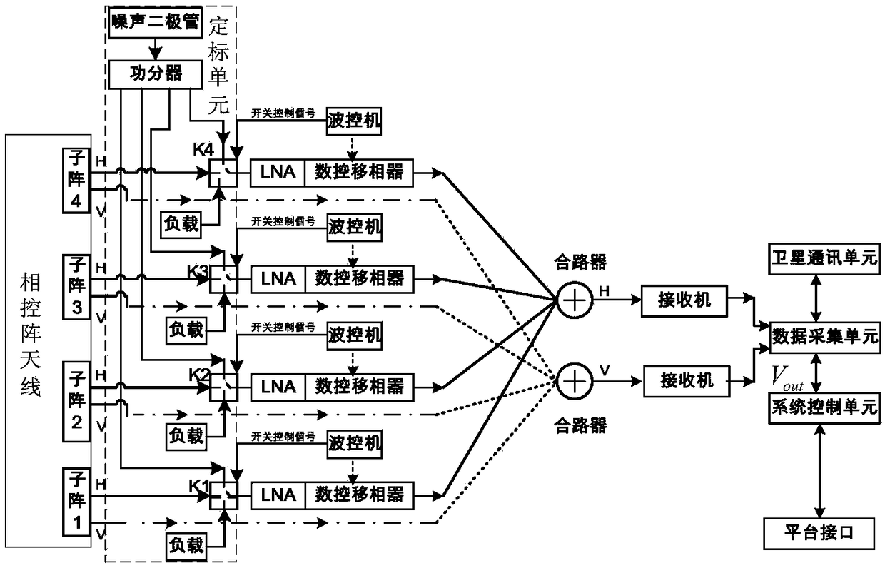
[0035] 4.1 Introduction to System Composition

[0036] The block diagram of the UAV-borne phased array antenna microwave radiometer system is attached figure 1 As shown, it consists of a phased array antenna, a calibration unit, a receiver, a wave control machine, a first-stage low-noise amplifier, a digitally con...


PUM


Abstract

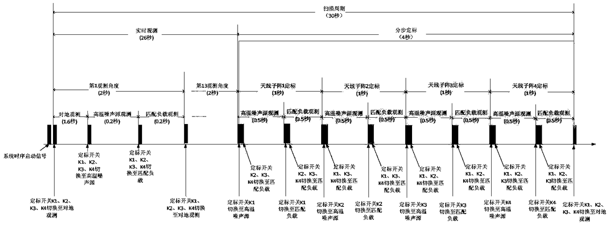
The invention discloses a step-by-step calibration system and method applied to a microwave radiometer of an unmanned airborne phased array antenna. The system comprise a noise diode, matching loads,a power divider and calibration switches, wherein the number n of the calibration switches is consistent with the number of subarrays of the phased array antenna; the calibration switches are single-pole three-throw switches; one path of input of each calibration switch is connected with one path of H polarization signal output by each subarray of the antenna; the noise diode provides a high-temperature signal needed for calibration, and n paths of signals are output to one input of input of each calibration switch through the power divider; each calibration switch is externally connected witha matched load, and a normal-temperature reference signal needed for two-point calibration is provided; three states of each calibration switch correspond to ground observation, high-temperature noise source observation and matching load observation respectively; and during operation, a beam control device controls the calibration switches to be switched according to a predesigned time sequence,and the ground observation and the two-point real-time calibration of different subarrays are completed within each scanning period.

Description

technical field [0001] The invention designs a calibration method for a phased array antenna microwave radiometer, and belongs to the technical field of space microwave remote sensing. Background technique [0002] The step-by-step calibration method of the phased array antenna microwave radiometer on the UAV provides support for the phased array antenna system microwave radiometer to obtain high calibration performance, and realizes the inversion of the system to generate seawater salinity, sea surface temperature and sea surface wind speed, etc. The basic parameters of the ocean provide guarantee, so that the system can meet the application requirements of real-time detection of my country's offshore environment, and provide important environmental information guarantee for maritime economic activities. [0003] The existing airborne radiometer calibration methods all use the traditional overall noise injection single-point calibration method, which can obtain a single cali...

Claims


Application Information

Patent Timeline
Patent Type & Authority Applications(China)
IPC IPC(8): G01S7/40
CPCG01S7/40
Inventor 余锐吕容川卢海梁党鹏举胡泰洋何征李浩
Owner XIAN INSTITUE OF SPACE RADIO TECH
Learn More