Virtual inductive reactance regulator and control method for realizing reactive power equalization of parallel inverter

A control method and inverter technology, applied in the field of microgrid, can solve problems such as power coupling, line impedance difference, reactive power sharing error, etc., and achieve the effect of increasing reliability, improving power quality, and realizing precise distribution

Pending Publication Date: 2019-01-08
SICHUAN UNIV
View PDF0 Cites 4 Cited by
  • Summary
  • Abstract
  • Description
  • Claims
  • Application Information

AI Technical Summary

Problems solved by technology

[0004] Based on the deficiencies in the prior art, the purpose of the present invention is to provide a solution based on the problem that the line impedance in the low-voltage microgrid

Method used


Image

  • Virtual inductive reactance regulator and control method for realizing reactive power equalization of parallel inverter
  • Virtual inductive reactance regulator and control method for realizing reactive power equalization of parallel inverter
  • Virtual inductive reactance regulator and control method for realizing reactive power equalization of parallel inverter

Examples


example (1

[0089] Both inverters adopt traditional droop control, and only supply power to load 1 within 0-1s: the active and reactive power of load 1 are 8kW and 10kVar respectively, and load 2 is put into power supply in the first second, and will be turned on in the second second. After its removal, the system stabilizes and returns to a load of only 1. The active and reactive power of load 2 are 8kW and 8kVar respectively.

[0090] Figure 8 shows the simulation results of the output voltage of the active power and reactive power inverter obtained when the traditional droop control is adopted.

[0091] Depend on Figure 8-a It can be seen from the active power simulation result shown in the figure that even though the traditional droop control can share the active power well, it takes a long time to achieve the equal share, which takes 0.4s, and the operation efficiency is low; Figure 8-b Comparing one phase of the output voltage of the two inverters, it can be seen that due to the...

example (2

[0093] Both inverters use the virtual inductive reactance regulator to calculate the virtual inductive reactance for power decoupling and eliminate line impedance difference, and the load switching is the same as in example (1).

[0094] see Figure 9-a~9-c .

[0095] The simulation results of inverter output voltage, active power and reactive power obtained by adopting the control method of the invention. In the figure, it can be seen that the introduction of virtual inductive reactance realizes power decoupling and eliminates the difference in equivalent line impedance between the two inverters. Figure 8-a , the transition time for equal sharing of active power is shortened, only 0.14s is needed, the output voltage difference between the two inverters is significantly smaller, and the effect of equal sharing of reactive power is significantly improved. Q 1 , Q 2 The relative error is within ±2%.


PUM


Abstract

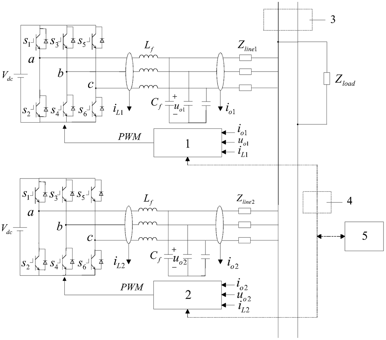
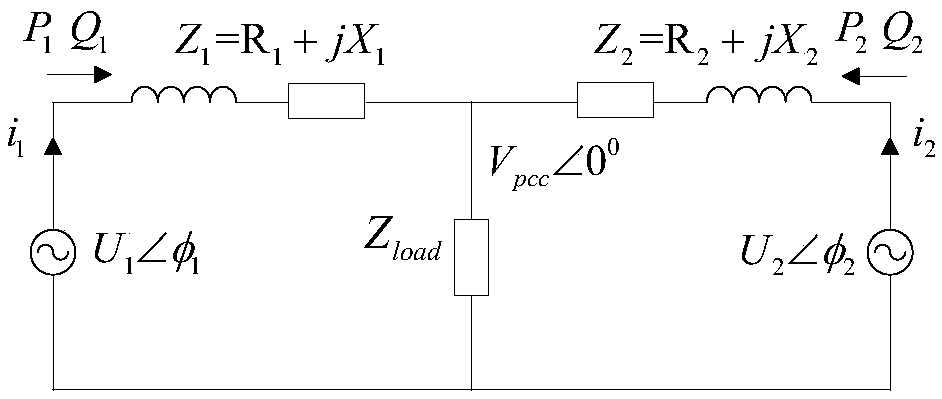
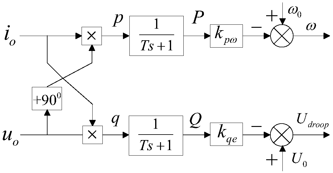
Virtual inductive reactance regulator and control method for realizing reactive power equalization of parallel inverter. Virtual inductive reactance regulator consists of subtractor, integrator and adder. The input of the subtractor is the output reactive power of the inverter and the rated reactive power of the inverter, and the absolute error of the output reactive power; The input of the integrator is the absolute error of reactive power and the adaptive part of the output virtual inductive reactance. The input of the adder is the output of the integrator and the reference virtual inductivereactance, and the output virtual inductive reactance. The virtual reactance regulator is installed in the local controller of the inverter, and the local controller and the central controller are interconnected through a low bandwidth communication line. The invention introduces a virtual inductive reactance into each inverter of a low-voltage microgrid and adds a virtual inductive reactance regulator, Reactive power is used to adjust the virtual inductance, which can achieve reactive power equalization without measuring line impedance parameters to achieve line impedance matching. Additional communication lines are not needed between inverters, and the plug-and-play characteristics of micro-grid inverters are preserved.

Description

(1) Technical field [0001] The invention belongs to the technical category of micro-grid, and relates to the balanced distribution of reactive power during parallel operation of inverters in low-voltage micro-grid isolated islands, in particular to a virtual inductive reactance regulator and a control method for realizing equal sharing of reactive power of parallel inverters. (2) Background technology [0002] In recent years, a large number of renewable energy sources have been connected to the power grid in the form of distributed power sources. Microgrids have increased the penetration rate of distributed power sources and increased the reliability of new energy power supply, which has attracted much attention. During the island operation of the microgrid, there is no voltage and frequency reference provided by the large grid, and the parallel inverter provides the voltage and frequency for the entire grid. Therefore, the inverter greatly affects the power quality of the m...

Claims


Application Information

Patent Timeline
IPC IPC(8): H02J3/18H02J3/38
CPCH02J3/382H02J3/18H02J3/388H02J2203/20Y02E40/30
Inventor 苗虹白小丹曾成碧白兴勇刘明陈博焦恒新
Owner SICHUAN UNIV
Why Eureka
Try Eureka