Plate turning extrusion device, and sludge dewatering system and method

A extrusion device and sludge dewatering technology, which is applied in the field of sludge dewatering system and flap extrusion device, can solve the problems of large environmental pollution and difficult treatment, and achieve the goal of improving sensitivity, improving dehydration efficiency and reducing labor intensity Effect

Inactive Publication Date: 2019-01-11
李文静
View PDF1 Cites 7 Cited by
  • Summary
  • Abstract
  • Description
  • Claims
  • Application Information

AI Technical Summary

Problems solved by technology

[0002] The pollution of sludge to the environment is relatively large, and its treatment is relatively difficult

Method used


Image

  • Plate turning extrusion device, and sludge dewatering system and method
  • Plate turning extrusion device, and sludge dewatering system and method
  • Plate turning extrusion device, and sludge dewatering system and method

Examples


Embodiment 1

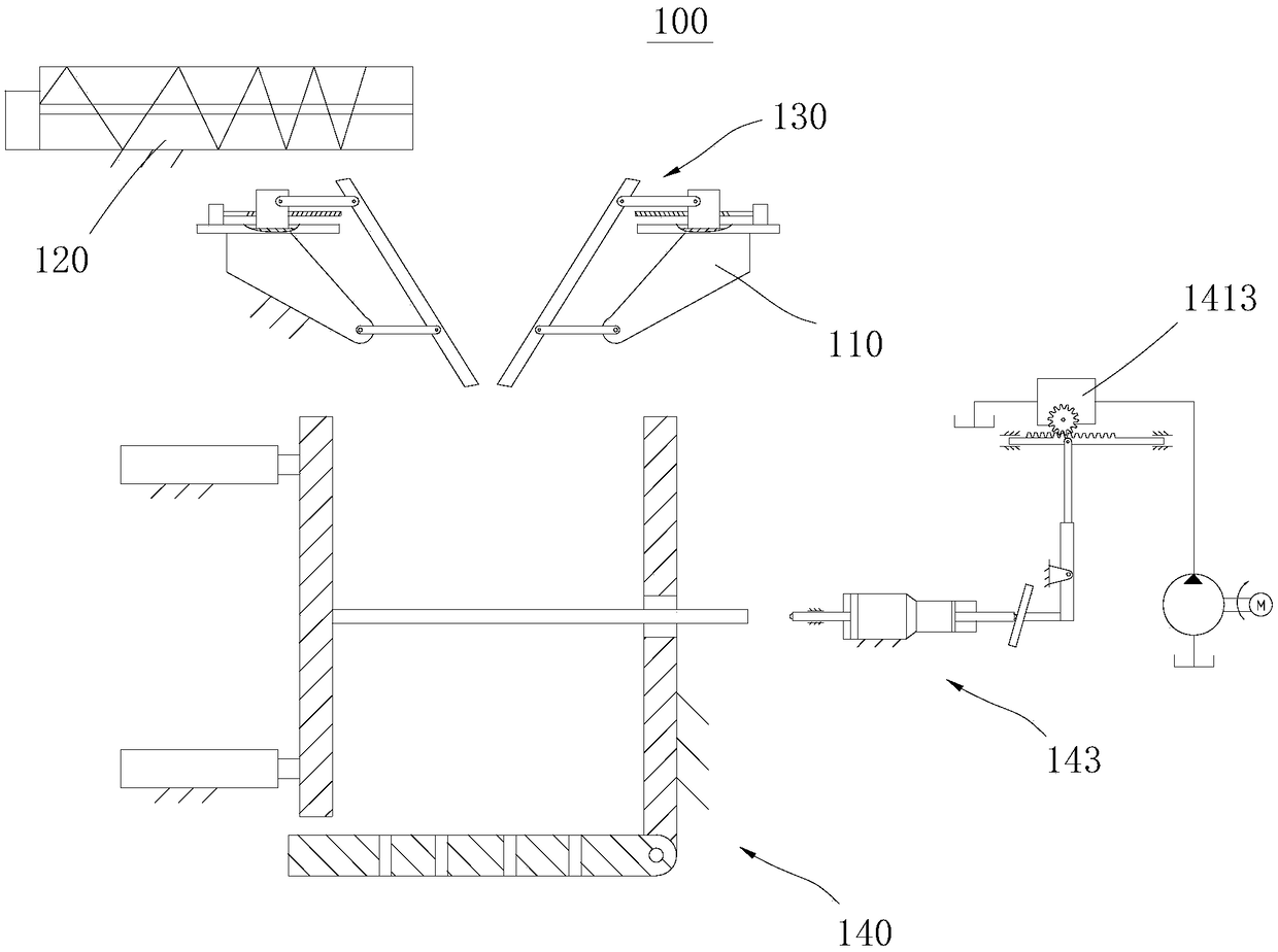
[0076] Please refer to figure 1 , this embodiment provides a sludge dewatering system 100, which is mainly used for dehydrating sludge with relatively high water content, so as to facilitate subsequent treatment. The above-mentioned dehydration system mainly includes a frame 110, a screw conveyor 120, a flap dehydrator 130 and a hydraulic dehydrator 140; the frame 110 is used to fix and install other components; the screw conveyor 120 is used to transport sludge to the flap dehydrator The preliminary dehydration is carried out in the hydraulic dehydrator 130, and the sludge after the preliminary dehydration falls into the hydraulic dehydrator 140 for deep dehydration.

[0077] Specifically, please continue to refer to figure 1 , the screw conveyor 120 is arranged horizontally and includes a conveying cylinder, a screw shaft and a driving motor. The conveying cylinder is arranged horizontally, one end of which is provided with a feed port, and the feed port is arranged facing...

Embodiment 2

[0100] A method for sludge dewatering, utilizing the sludge dewatering system 100 provided in embodiment 1; comprising the following steps:

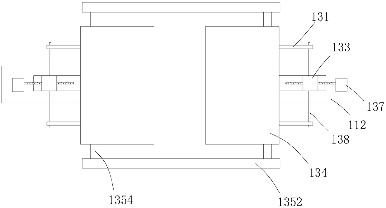
[0101] a. Adjust the system to the initial state; specifically, adjust the overflow valve 1413 so that the oil supply pressure of the hydraulic system 141 is between 0.5MPA-1MPA; adjust the two extrusion devices so that the bottom of the two flaps 134 the smallest gap between

[0102] b. start the screw conveyor 120, and feed the sludge into the screw conveyor 120;

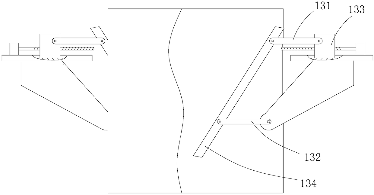
[0103] c. Preliminary dehydration: start two sliding drive mechanisms 137, so that the upper parts of the two extrusion plates are close to each other, and perform preliminary extrusion dehydration;

[0104] d. Start the two sliding drive mechanisms 137 to reset the two squeeze plates; then start the rotation drive mechanism to make the two squeeze plates move away from each other; make the sludge fall into the hydraulic dehydrator 140 below;

[0105] e. Deep dehydration, ...


PUM


Abstract

The invention provides a plate turning extrusion device, and a sludge dewatering system and method, wherein the plate turning extrusion device is mainly used for dewatering sludge with high water content for subsequent treatment. The dewatering system mainly includes a rack, a screw conveyor, a plate turning dewatering machine and a hydraulic dewatering machine; the rack is used for fixing and mounting other parts; the screw conveyor is used for transporting the sludge to the plate turning dewatering machine for preliminary dewatering, and the sludge after preliminary dewatering falls into thehydraulic dewatering machine and is subjected to deep dewatering. The method adopts the system and includes the steps of adjusting the system to the initial state and the like. With use of the dewatering system and method, not only is the dewatering rate high, but also the labor intensity of workers is reduced and the dewatering efficiency is improved.

Description

technical field [0001] The invention relates to the field of environmental protection equipment, in particular to a flap extrusion device, a sludge dewatering system and a method. Background technique [0002] The pollution of sludge to the environment is relatively large, and its treatment is also relatively difficult. When treating sludge, it is generally necessary to dehydrate the sludge first; after dehydration, use corresponding equipment to treat the sewage and the dehydrated sludge respectively. [0003] Therefore, providing a flap extrusion device, sludge dewatering system and method is of great significance to environmental protection. Contents of the invention [0004] An object of the present invention is to provide a sludge dewatering system capable of effectively dewatering sludge. [0005] The purpose of the present invention is also to provide a sludge dewatering method, which adopts the above sludge dewatering system. [0006] The present invention is ac...

Claims


Application Information

Patent Timeline
Patent Type & Authority Applications(China)
IPC IPC(8): C02F11/121
CPCC02F11/121
Inventor 李文静曹福来
Owner 李文静
Why Eureka
Try Eureka