
Extraction drilling machine for landfill gas recovery

A technology for gas recovery and landfill, which is applied to drill pipes, drill pipes, mining fluids, etc., can solve problems such as increased workload, soil pollution, waste of resources, etc., to ensure work efficiency, simple work flow, and reasonable structure settings. Effect

Active Publication Date: 2019-01-11
嘉兴金旅燕科技有限公司
View PDF13 Cites 2 Cited by
  • Summary
  • Abstract
  • Description
  • Claims
  • Application Information

AI Technical Summary

Problems solved by technology

[0002] Nowadays, some agricultural solid wastes are often disposed of by landfill. These landfills will rot under the ground for a long time and will produce a large amount of waste gas. If these waste gases are not treated, they will pollute the soil. Moreover, the exhaust gas produced by these agricultural wastes is usually recyclable gas, such as biogas. If it is not recycled, it will cause a waste of resources. Nowadays, drilling equipment is used to drill channels at the landfill, and exhaust gas is discharged through exhaust equipment. In order to achieve the purpose of easy operation, but it still has the following disadvantages in actual use:
[0003] 1. Drilling equipment and air extraction equipment are required to work, and the required equipment and operating procedures are complicated, which cannot be integrated and inconvenient to operate;
[0004] 2. During the period when the drilling equipment is drilled and the air extraction equipment is inserted into the landfill, it is easy to cause a large amount of exhaust gas to overflow, pollute the external air environment, and easily cause physical injury to the staff;
[0005] 3. When the rotary head of the drilling equipment is pulled out, the drilled air hole is easy to collapse and close, so it needs to be drilled again, which increases the workload

Method used


Image

  • Extraction drilling machine for landfill gas recovery
  • Extraction drilling machine for landfill gas recovery
  • Extraction drilling machine for landfill gas recovery

Examples


Embodiment Construction

[0026] The following will clearly and completely describe the technical solutions in the embodiments of the present invention with reference to the accompanying drawings in the embodiments of the present invention. Obviously, the described embodiments are only some, not all, embodiments of the present invention. Based on the embodiments of the present invention, all other embodiments obtained by persons of ordinary skill in the art without making creative efforts belong to the protection scope of the present invention.

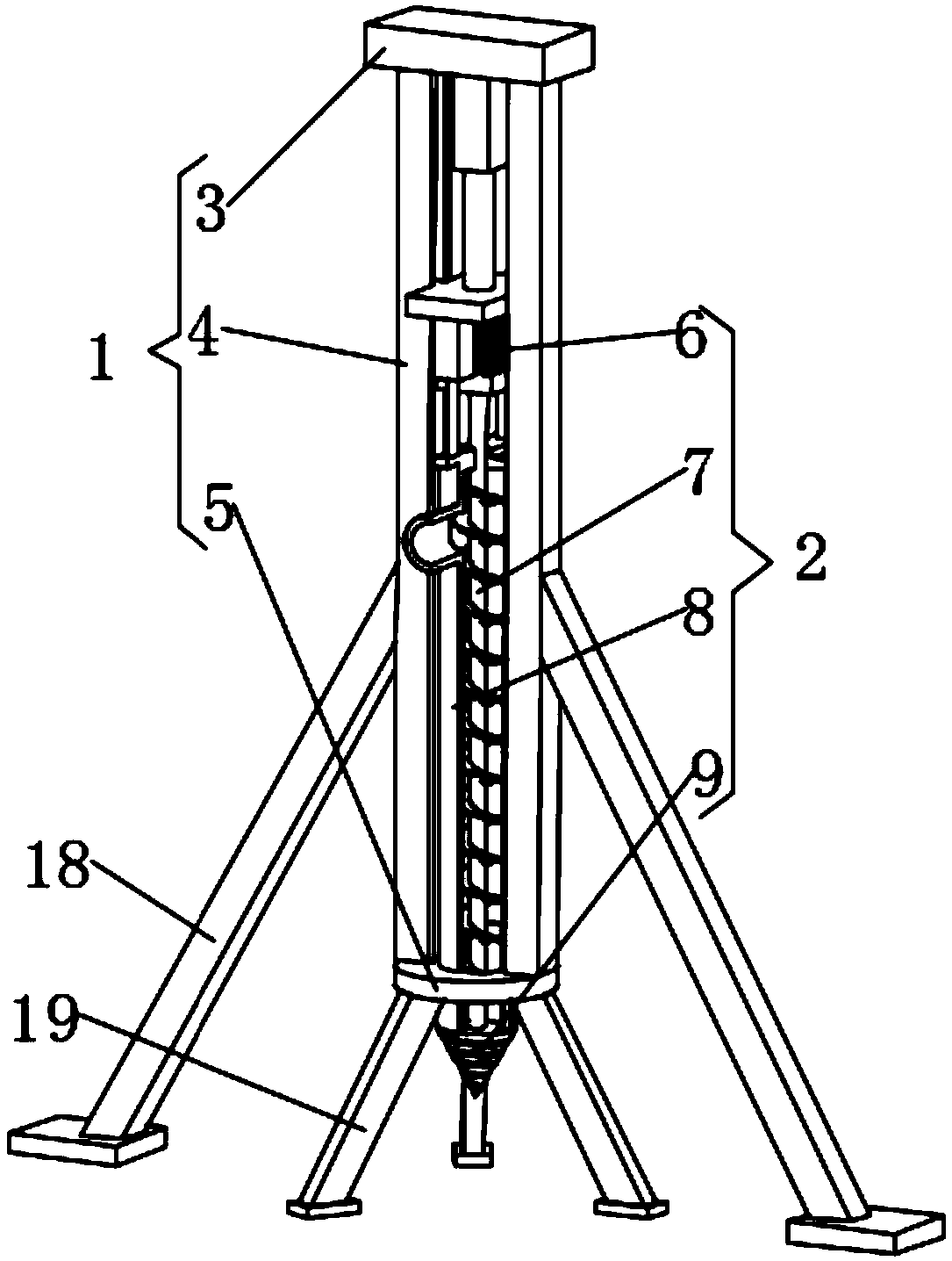
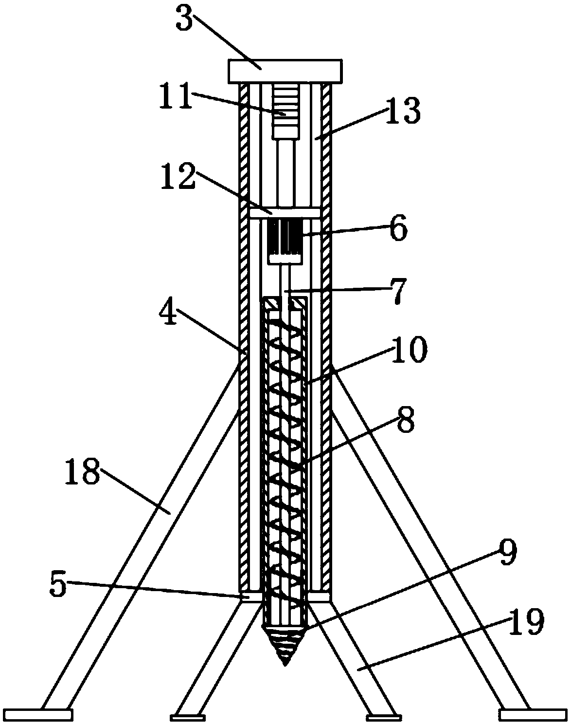
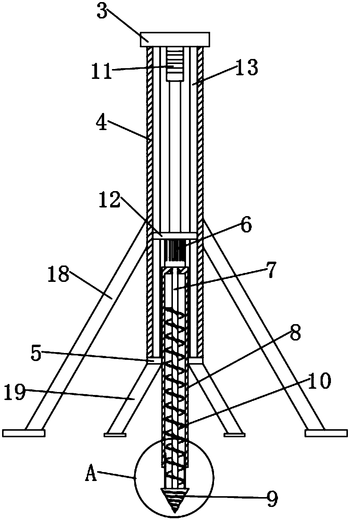
[0027] see Figure 1-7 , the present invention provides a technical solution: an extraction drilling rig for landfill gas recovery, including a support mechanism 1 and a working mechanism 2, the support mechanism 1 includes a main support top plate 3, guide columns 4 and a bottom support frame 5, the working Mechanism 2 comprises motor 6, driving rod 7, air guide cylinder 8 and drill bit 9, and guide post 4 is vertically symmetrically provided with two, and th...


PUM


Abstract

The invention discloses an extraction drilling machine for landfill gas recovery, which comprises a support mechanism and a working mechanism, wherein the support mechanism includes a main supportingtop plate, a guide column and a bottom supporting frame, and the working mechanism includes a motor, a driving rod, a gas guide cylinder and a drill bit. In the working mechanism of the invention, thedriving rod connected with the drill bit is externally sleeved with the gas guide cylinder, and the outer wall of the driving rod is provided with a helical blade shaped gas extracting blade. When the driving rod rotates, the drill bit can be driven to drill a hole, the gas extracting blade can further enable the gas guide cylinder to have an upward extraction force, so that the waste gas can bedirectly extracted when the drill bit drills to the waste gas, the working process is enabled to be simple, and there is no need to replace equipment. In addition, the extraction drilling machine doesnot result in great leakage of the waste gas, thereby protecting the good working environment.

Description

technical field [0001] The invention relates to the technical field of landfill gas recovery devices, in particular to an extraction drilling rig for landfill gas recovery. Background technique [0002] Nowadays, some agricultural solid wastes are often disposed of by landfill. These landfills will rot under the ground for a long time and will produce a large amount of waste gas. If these waste gases are not treated, they will pollute the soil. Moreover, the exhaust gas produced by these agricultural wastes is usually recyclable gas, such as biogas. If it is not recycled, it will cause a waste of resources. Nowadays, drilling equipment is used to drill channels at the landfill, and exhaust gas is discharged through exhaust equipment. In order to achieve the purpose of easy operation, but it still has the following disadvantages in actual use: [0003] 1. Drilling equipment and air extraction equipment are required to work, and the required equipment and operating procedures...

Claims


Application Information

Patent Timeline
Patent Type & Authority Applications(China)
IPC IPC(8): E21B15/00E21B17/22E21B7/00E21B43/00
CPCE21B7/00E21B15/00E21B15/006E21B17/22E21B43/12
Inventor 李挺佳吴哲铭张荣法
Owner 嘉兴金旅燕科技有限公司
Learn More