Coal mining machine secondary negative pressure dust reducer

A secondary negative pressure, shearer technology, applied in the field of dust reduction and dust removal, can solve problems such as poor dust removal effect, easy blockage of atomizing nozzles, and harsh underground working environment, so as to improve dust reduction efficiency, improve water source utilization, and facilitate maintenance effect

Inactive Publication Date: 2019-01-11
ZOUCHENG YANKUANG TAIDE IND & TRADE CO LTD
View PDF6 Cites 0 Cited by
  • Summary
  • Abstract
  • Description
  • Claims
  • Application Information

AI Technical Summary

Problems solved by technology

At present, the existing underground coal mining machine spray dust reduction and dust prevention devices generally use high-pressure water to spray directly, and the water mist and coal dust come into contact with each other to reduce dust, and some coal dust is blown everywhere by the water mist before it arrives. Coal dust cannot be effectively captured, and the dust removal effect is poor
In order to carry out secondary treatment of coal dust flying everywhere, atomizing nozzles are usually used in conjunction with certain equipment for dust reduction treatment. The underground working environment is harsh, and the atomizing nozzles are easily blocked during use, and water resources cannot be recycled for reuse. , the effect of secondary treatment of coal dust to reduce dust is often unsatisfactory, so a secondary negative pressure dust suppressor for coal mining machines was invented to overcome the above difficulties

Method used


Image

  • Coal mining machine secondary negative pressure dust reducer
  • Coal mining machine secondary negative pressure dust reducer
  • Coal mining machine secondary negative pressure dust reducer

Examples


Embodiment Construction

[0021] The technical solutions in the embodiments of the present invention will be clearly and completely described below in conjunction with the accompanying drawings in the embodiments of the present invention. Obviously, the described embodiments are only a part of the embodiments of the present invention, rather than all the embodiments. Based on the embodiments of the present invention, all other embodiments obtained by those of ordinary skill in the art without creative work shall fall within the protection scope of the present invention.

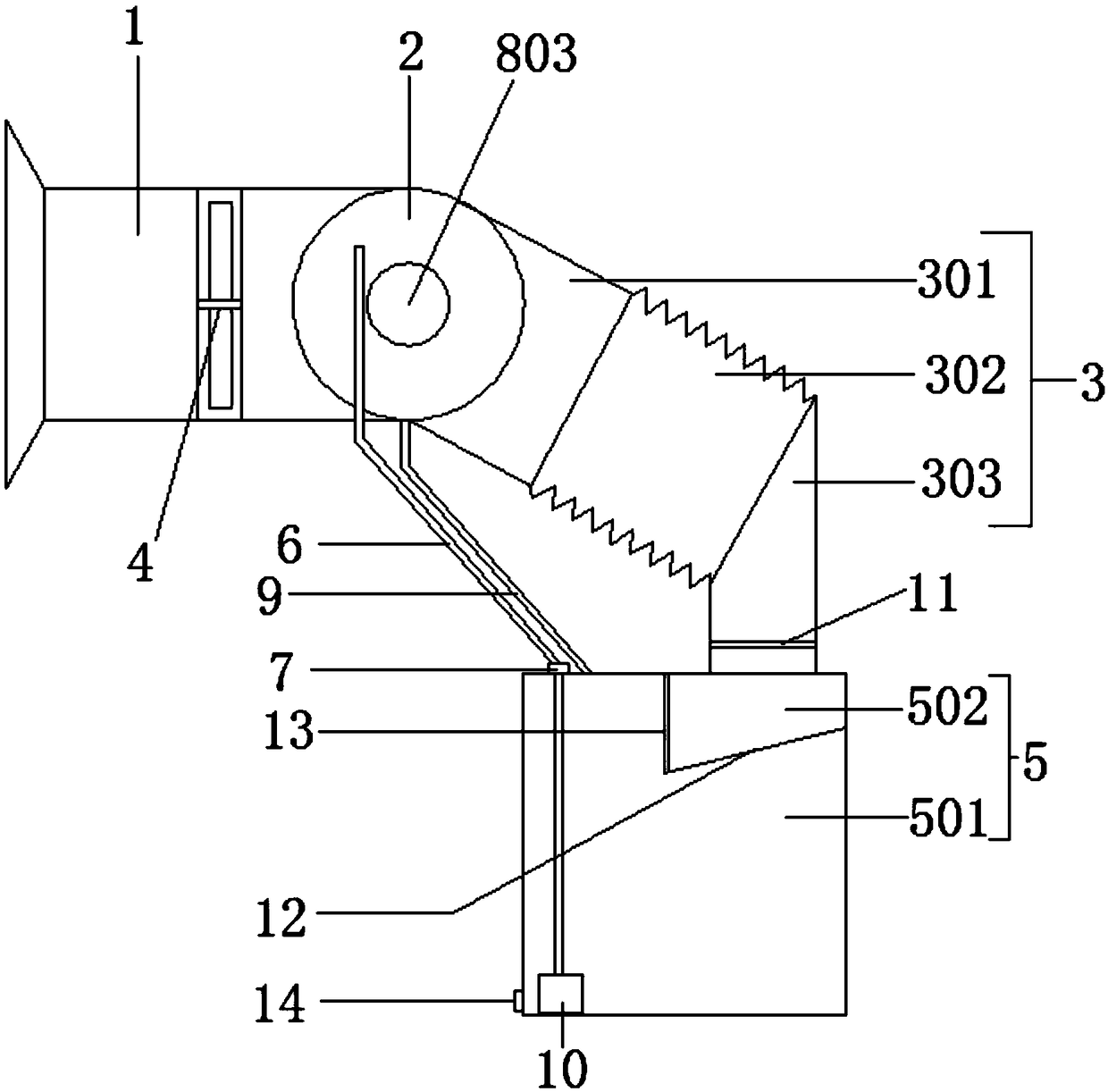
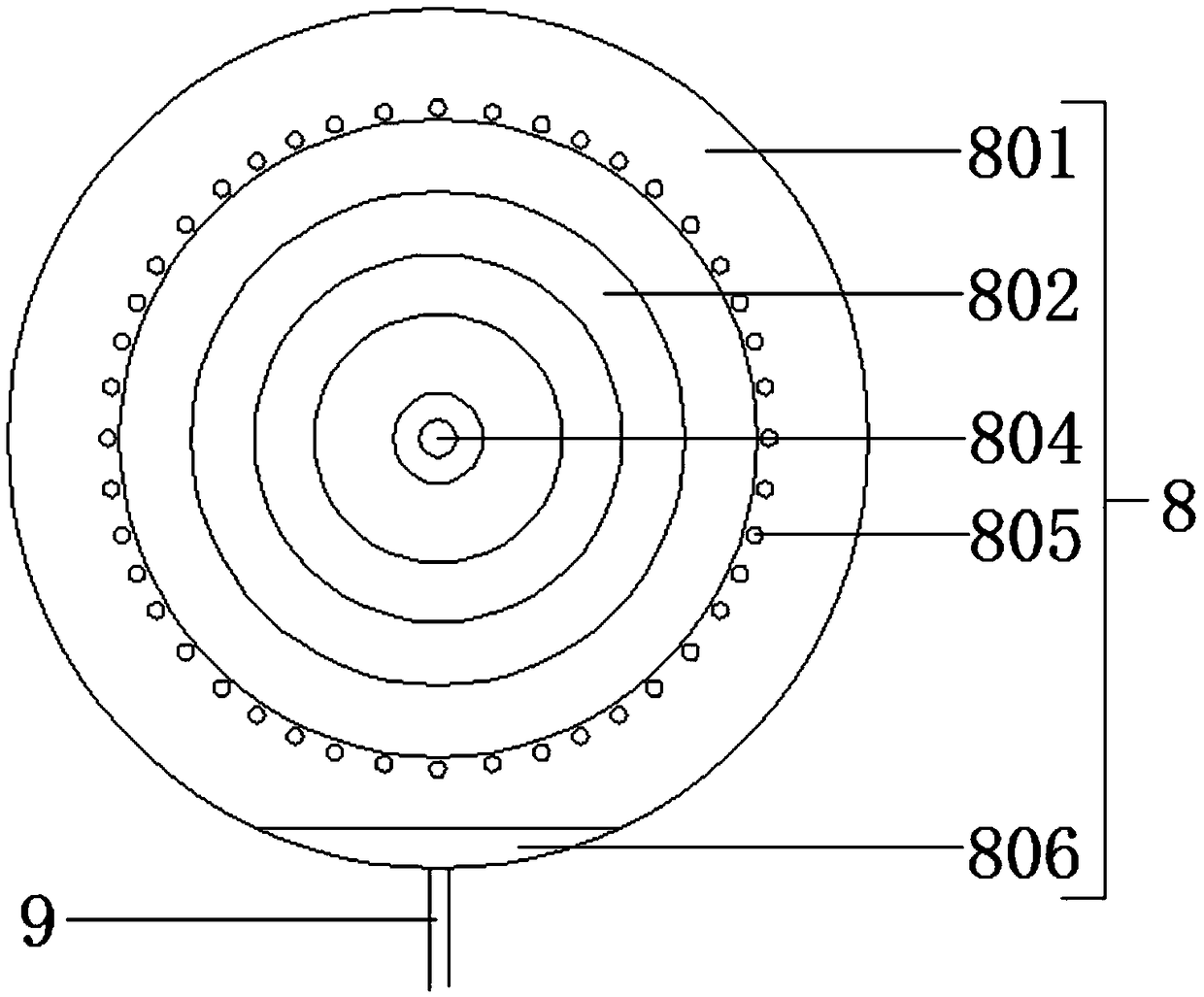
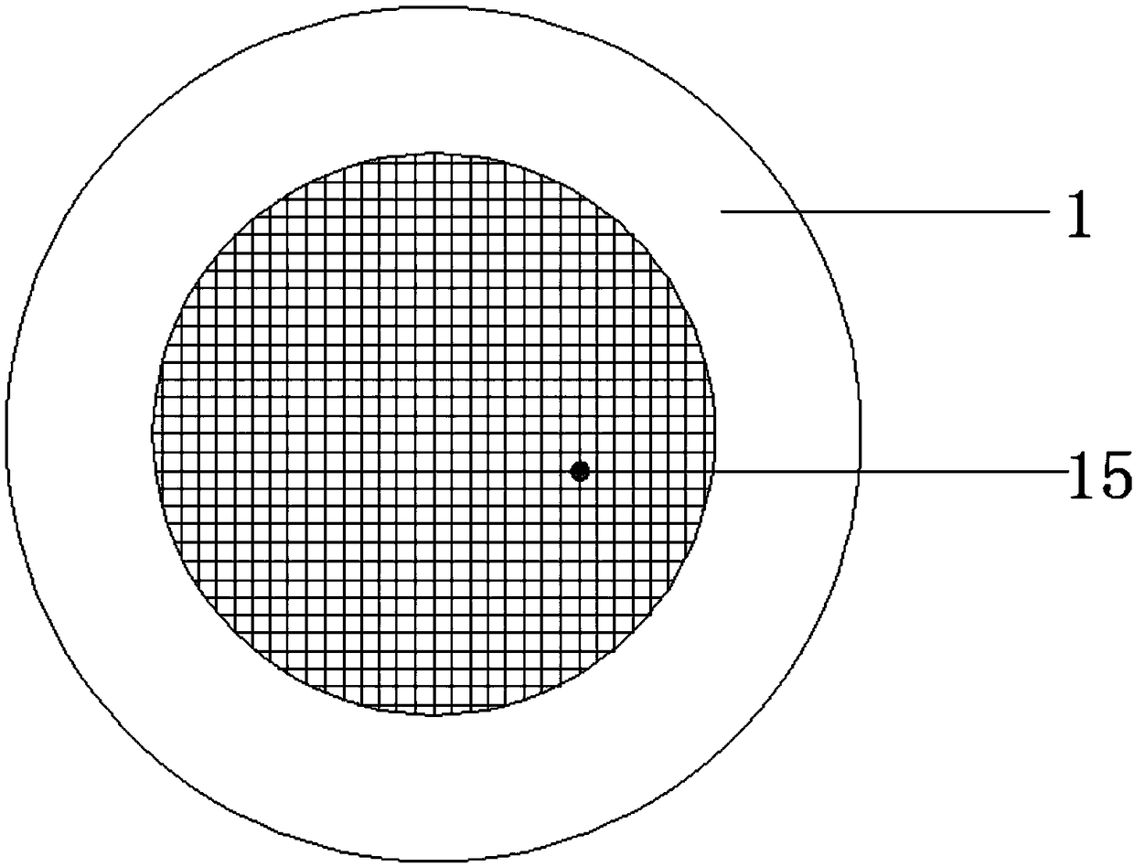
[0022] Such as Figure 1-3 As shown, the secondary negative pressure dust reducer of the coal shearer includes an air inlet pipe 1, a dust reduction chamber 2 and an exhaust pipe 3. The air inlet of the air inlet pipe 1 is horn-shaped, and a third filter is provided at the outlet of the air inlet 15. The air inlet pipe 1 is connected to the dust reduction chamber 2, the dust reduction chamber 2 is connected to the exhaust pipe 3, the ai...


PUM


Abstract

The invention provides a coal mining machine secondary negative pressure dust reducer. The secondary negative pressure dust reducer comprises an air inlet tube, a dust depositing chamber and an air exhaust tube, the air inlet tube is connected to the dust depositing chamber, the dust depositing chamber is connected to the air exhaust tube, and the air inlet tube is provided with an exhaust fan. The dust reduce is characterized in that: the dust depositing chamber is in a circular shape, a centrifugal dust depositing device is installed, and the air exhaust tube is connected with a water tank,the water tank and the dust depositing chamber are connected by a water supply pipe, and the water supply pipe is connected to the centrifugal dust depositing device through the dust depositing chamber; the water supply pipe is provided with a flow regulating valve, and the flow regulating valve is installed on the water tank. The dust reducer sucks the coal dust into the dust depositing chamber through the exhaust fan, and performs the second dust depositing through the centrifugal dust depositing device, and improves the dust depositing efficiency, no clogging of a traditional atomizing nozzle is generated, which is convenient for maintenance; the dust reducer can also recycle and reuse water resources, and effectively reuses the water that is not fully utilized by the centrifugal dust depositing device and the led out by the air exhaust tube, and the utilization rate of the water source is increased.

Description

Technical field [0001] The invention relates to the technical field of dust removal and dust reduction used in coal mining machines, in particular to a secondary negative pressure dust reducer for coal mining machines. Background technique [0002] With the rapid development of my country's economic construction, energy demand is huge. As the main source of my country's energy supply, coal resources will be difficult to change for a long time in the future, resulting in the continuous development of the coal industry in the direction of mechanization and automation. At present, the spray dust reduction and dust prevention devices of the existing underground coal shearers generally use high-pressure water to spray directly. The water mist and coal dust contact at one time to reduce dust, and some coal dust is blown up before the water mist arrives. The coal dust cannot be captured effectively, and the dust removal effect is poor. In order to carry out secondary treatment of coal ...

Claims


Application Information

Patent Timeline
IPC IPC(8): E21C35/22
CPCE21C35/22
Inventor 郑春梅张长运张仁同王衍青王保勤张松林
Owner ZOUCHENG YANKUANG TAIDE IND & TRADE CO LTD
Why Eureka
Try Eureka