Geological radar detecting scheme for back-filled grouting of shield segment in water-rich gravel stratum

A technology of shield segment and geological radar, which is applied to measurement devices, radio wave measurement systems, reflection/re-radiation of radio waves, etc. Accurate results

Active Publication Date: 2019-01-11
广西有色勘察设计研究院
View PDF4 Cites 8 Cited by
  • Summary
  • Abstract
  • Description
  • Claims
  • Application Information

AI Technical Summary

Problems solved by technology

[0003]The construction process of the shield tunneling method is complicated, and the problems will be different when encountering different types of strata, such as the area where more than 60% of the tunnel in the Nanning rail transit project Located in the water-rich boulder formation, the formation has the characteristics of high water content, large pores, poor self-stability and strong water permeability. It is a typical binary loose structure mixed with pebbles with high uniaxial compressive strength. Severe wear and tear is prone to problems such as gushing and delayed settlement. If the grouting of the wall of the soil layer is not timely or the grouting effect is not ideal, the stress will be redistributed, which will cause rock and soil instability and damage. During the construction process, strict Maintaining the balance of water and soil pressure on the excavation surface according to the specifications can generally avoid accidents such as ground subsidence. However, since the outer diameter of the shield segment is smaller than the excavation diameter of the shield machine cutterhead, a certain gap is generated during construction, and the water-rich boulder layer During grouting, defects such as cavities and lack of compaction are easy to occur, and the stress release of the surrounding rock of the tunnel can easily induce geological disasters such as ground subsidence. take action to deal with
[0004]Aiming at the post-grouting effect detection scheme of the shield segment wall, the traditional method is to observe whether the segment has water seepage or use the drilling method to verify the post-grouting effect of the shield segment wall. Grout quality, these traditional methods are not only time-consuming and labor-intensive, but also the drilling method will bring some damage to the shield segment, and cannot comprehensively detect and evaluate the effect of grouting, so the current detection scheme is to use geological radar to detect The non-destructive testing technology is a non-destructive geophysical detection method that uses high-frequency electromagnetic waves to determine the distribution of underground media. It is mainly used in the fields of tunnel detection, roadbed pavement detection and port wharf detection. It is applied to the subway shield tunnel During the test and detection of the grouting situation behind the wall, by detecting the distribution of the grouting body in the radial direction and length direction of the tunnel and the gap between the grouting body and the tunnel segment (that is, the thickness and defects of the grouting body), thereby Quickly grasp the filling situation and construction quality of the grouting fluid between the segments and the soil, and provide an important basis for the settlement control, secondary grouting and compensation grouting of the shield tunnel in the subsequent construction. Due to the influence of various on-site environmental magnetic fields, radar wave interference and other factors, the displayed radar wave signal is not a real reflection of the situation, such factors include shield tunnel space constraints, on-site radar wave scattering, non-radar electromagnetic field sources, The secondary radar reflection wave of the structural segment is superimposed on the grouting layer reflection wave, etc., so the response signal detected by the ground radar cannot correctly identify the thickness and defects of the grouting layer behind the shield segment wall, and it is difficult for the detection work and Late shield tunneling work has an impact

Method used


Image

  • Geological radar detecting scheme for back-filled grouting of shield segment in water-rich gravel stratum
  • Geological radar detecting scheme for back-filled grouting of shield segment in water-rich gravel stratum
  • Geological radar detecting scheme for back-filled grouting of shield segment in water-rich gravel stratum

Examples


Embodiment 1

[0035] Example 1 Nanning Rail Transit Line 2 Chaoyang Square ~ Railway Station

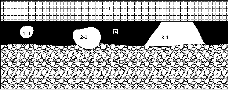
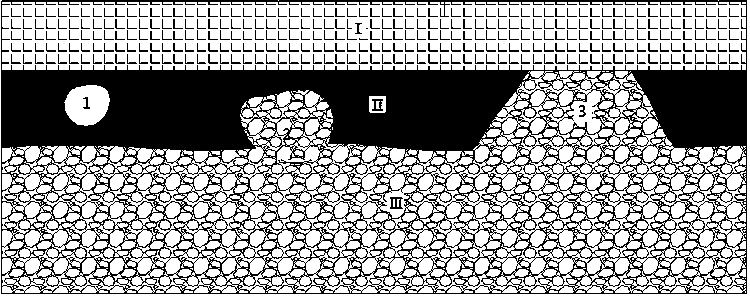
[0036] 1) Detect on-site interference sources, mainly including wire (cable) interference, segment joint interference, segment screw interference, and tunnel ring structure interference to radar signals. Wire (cable) interference is a typical hyperbolic shape on radar. Segment seam interference is in the form of strong reflection on the radar, and the location is relatively fixed. Segment bolts are strong reflection in the radar and decay slowly. Because the tunnel is ring-shaped, the radar antenna is not absolutely shielded, and a small amount of energy is scattered into the air and reflected by the inner wall of the tunnel to form a certain amount of interference on the radar. However, this type of interference energy is relatively weak, and the interference has already exceeded the target detection layer. time, so the interference to the on-site detection is limited. The secondary reflection o...

Embodiment 2

[0050] Example 2 Nanning Rail Transit Line 2 No. 33 Middle School ~ Xiuxiang Station

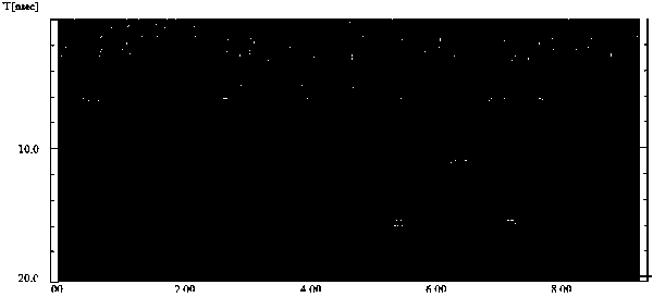
[0051] The model of the shield segment at this station is X-4, and the strength of the shield is C50. The Italian K2-FW radar is used for detection on site. The electromagnetic wave reflection signal of the grouting layer forms interference. The wave velocity of the detection shield segment is 11.2cm / ns, the wave velocity of the grouting layer is 8.7cm / ns, the sampling time window is 40ns, the sampling point distance is 3.2cm, and the radar antenna is 400MHz. According to the wave velocity calibrated on site value, the thickness of the segment is calculated as 30cm, the thickness of the grouting layer is 16-21cm, there is no radar reflection clutter behind the grouting layer, the surrounding rock properties on the surface are uniform, and the radar reflection wave between the grouting layer and the surrounding rock is continuous in phase, There is no obvious hyperbolic reflection, and there ...


PUM


Abstract

The invention discloses a geological radar detecting scheme for back-filled grouting of a shield segment in a water-rich gravel stratum. The scheme comprises the following steps: 1) marking and recognizing various interference sources in a detected site, and analyzing the radar signal characteristics thereof; 2) detecting a relative dielectric constant, a dielectric wave velocity, and a resistivity of a shield segment, a grouting layer, and the water-rich gravel stratum, confirming the applicability of a geological radar, and calibrating wave velocities corresponding to different antenna frequencies; 3) building grouting body defect models by a geological radar detecting test platform for grouting a post wall of the shield segment in the water-rich gravel stratum, and analyzing radar signal characteristics of each defect model; 4) estimating and selecting geological radar detecting parameters; 5) distributing measuring lines; and 6) detecting post processing. The geological radar detecting scheme for the back-filled grouting of the shield segment in the water-rich gravel stratum can accurately detect the thickness, the defects, and the distribution of the post wall grouting layer of the shield segment, effectively avoids various interference, and can accurately, rapidly and comprehensively identify.

Description

technical field [0001] The invention relates to the technical field of tunnel shield construction engineering survey, in particular to a geological radar detection scheme for post-grouting of shield segment walls in water-rich round gravel layers. Background technique [0002] The shield method is currently the main method used in the construction of urban underground rail transit. It is to propel the shield machine in the ground, and to support the surrounding rock through the shield casing and segments to prevent collapse into the tunnel. A mechanized construction method in which the soil is excavated with a cutting device in front of the tunnel, transported out of the tunnel by excavation machinery, pushed in by jacks at the rear, and assembled with precast concrete segments to form a tunnel structure. Stratum loss caused by shield tunneling, reconsolidation of disturbed or shear-damaged reshaped soil around shield tunnels, and groundwater infiltration are important reaso...

Claims


Application Information

Patent Timeline
Patent Type & Authority Applications(China)
IPC IPC(8): G01S7/41G01S13/88
CPCG01S7/41G01S13/885Y02A90/30
Inventor 闫清武徐初来翁敦贤马富安唐甫韦益华黄尚俊姜明强师虎峰何其智何鎏
Owner 广西有色勘察设计研究院
Why Eureka
Try Eureka