
A power supply system for photovoltaic buildings

A photovoltaic building and power supply system technology, applied in photovoltaic power generation, photovoltaic module support structures, photovoltaic modules, etc., can solve problems such as the scope of manual monitoring operations, improve photoelectric conversion efficiency, ensure long-term high-efficiency work, and improve conversion efficiency Effect

Inactive Publication Date: 2019-01-11
广东南控电力有限公司
View PDF5 Cites 0 Cited by
  • Summary
  • Abstract
  • Description
  • Claims
  • Application Information

AI Technical Summary

Problems solved by technology

[0003] The purpose of the present invention is to provide a power supply system for photovoltaic buildings. By providing a grid-connected energy storage machine and load balancing, the grid-connected energy storage machine can store excess power generation, increase the proportion of self-generation and self-use, and apply to photovoltaic self-use. In the application places where the surplus is connected to the grid, the electricity price for self-use is much more expensive than the grid electricity price, and the peak electricity price is much more expensive than the wave-level electricity price, the scattered energy is converted into electric energy on the spot, and then supplied to the local load nearby to realize an autonomous system of self-control, protection and management. It can be operated in parallel with the external power grid or isolated to solve the problem that most of the photovoltaic power supply systems on the market currently require manual monitoring and operation and have a small application range

Method used


Image

  • A power supply system for photovoltaic buildings
  • A power supply system for photovoltaic buildings
  • A power supply system for photovoltaic buildings

Examples


Embodiment 1

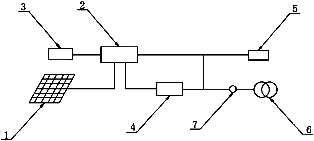
[0021] The present invention provides such Figure 1-3 The power supply system for a photovoltaic building shown includes a photovoltaic building 1, the photovoltaic building 1 is connected to a grid-connected energy storage machine 2 through a power grid, and the grid-connected energy storage machine 2 is connected to a battery 3 through a conductive grid, so The grid-connected energy storage machine 2 is connected to a grid-connected inverter 4 and a load balancer 5 through a power supply network, the grid-connected inverter 4 is connected to a grid 6 through a power distribution network, and the load balancer 5 and the grid 6 are connected through a transmission The cables are connected, and a plurality of current sensors 7 are installed on the distribution network between the grid 6 and the grid-connected inverter 4 .

[0022] The grid-connected energy storage machine 2 is internally equipped with a DC filter, a PCS bidirectional converter, an intelligent switch, a CPU pro...

Embodiment 2

[0026] The grid-connected inverter 4 includes a first DC / DC41, DC / AC42, an AC filter 43 and a second DC / AC44, the first DC / DC41 is connected in series with the grid-connected energy storage machine 2, and the first DC / AC42 and AC filter 43 are respectively connected in series on the outside of DC / DC41, an intelligent switching switch is provided between the first DC / DC41 and DC / AC42, and an intelligent switching switch is provided between the DC / AC42 and AC filter 43. To switch the switch, the second DC / AC44 is connected in parallel between the grid-connected energy storage machine 2 and the first DC / DC41, and the second DC / AC44 is connected in series between the first DC / DC41 and DC / AC42.

[0027] The grid-connected inverter 4 is connected in parallel with the grid 6, and the output of the grid-connected inverter 4 is used as a current source, and the parallel connection of the grid-connected inverter 4 and the grid 6 can be regarded as a parallel operation of a current source...

Embodiment 3

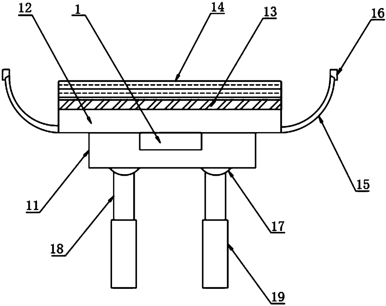
[0031] The photovoltaic building 1 includes a support base 11, a mounting plate 12, a ventilation panel 13, a BIPV assembly 14, a sunshield 15, a photosensitive sensor 16, a hinge block 17, a hydraulic lifting rod 18 and a base 19, and the number of the support base 11 is set to Multiple, the top of the support seat 11 is provided with a mounting plate 12, the top of the mounting plate 12 is provided with a ventilation panel 13, the top of the ventilation panel 13 is provided with a BIPV assembly 14, and both sides of the installation panel 12 are provided with light-shielding The shape of the shading plate 15 is arc-shaped, the top of the shading plate 15 is provided with a photosensitive sensor 16, the bottom of the support seat 11 is evenly provided with a hinge block 17, and the bottom of the hinge block 17 is provided with a hydraulic lift Rod 18, the hydraulic lifting rod 18 is hinged with the hinge block 17, and the bottom of the hydraulic lifting rod 18 is fixed with a ...


PUM


Abstract

The invention discloses a power supply system of a photovoltaic building, including photovoltaic buildings. The photovoltaic building is connected with a grid-connected energy storage machine througha transmission network, the grid-connected energy storage machine is connected with a battery through a conductive network, the grid-connected energy storage machine is connected with a grid-connectedinverter and a load balancing through a power supply network, the grid-connected inverter is connected with a power network through a distribution network, and the load balancing and the power network are connected with each other through a transmission cable. As that grid-connected energy storage device and the load balan device are provided, Grid-connected energy storage device can store excessenergy generation, Increase the proportion of spontaneous self-use, as that photovoltaic device is use for photovoltaic spontaneous self-use. The self-used electricity price is much more expensive than the on-grid electricity price, and the wave crest electricity price is much more expensive than the wave level electricity price. The autonomous system which converts the dispersed energy into electric energy locally, and then supplies the local load nearby, realizes the self-control, protection and management, can not only run in parallel with the external power grid, but also in isolation.

Description

technical field [0001] The invention relates to the field of photovoltaic power supply, in particular to a power supply system for photovoltaic buildings. Background technique [0002] A photovoltaic power generation system refers to a power generation system that directly converts light energy into electrical energy without going through a thermal process. Its main components are solar cells, batteries, controllers and inverters. It is characterized by high reliability, long service life, no pollution to the environment, independent power generation and grid-connected operation. Solar power generation generally refers to solar photovoltaic power generation, referred to as "photoelectricity". Photovoltaic power generation is a technology that directly converts light energy into electrical energy by using the photovoltaic effect at the semiconductor interface. The key element of this technology is the solar cell. The solar cells are packaged and protected after being conne...

Claims


Application Information

Patent Timeline
IPC IPC(8): H02J7/35H02J3/38H02S20/32H02S40/42
CPCH02J3/383H02J7/35H02S20/32H02S40/425Y02B10/10Y02E10/56
Inventor 刘香峰叶召阳黄俊华叶明星林顺进
Owner 广东南控电力有限公司
Learn More