Laser cutting machine turbocharging dust removal and noise reduction device

A laser cutting machine, turbocharging technology, applied in laser welding equipment, welding/welding/cutting items, mechanical equipment, etc., can solve the problem of oxidation dust, smoke and airflow impact noise, affecting the operating environment of workers, affecting workers' health, etc. problems, to facilitate collection and recycling, improve the working environment, and reduce noise.

Active Publication Date: 2019-01-15
赣州市畅达电梯销售有限公司
View PDF5 Cites 6 Cited by
  • Summary
  • Abstract
  • Description
  • Claims
  • Application Information

AI Technical Summary

Problems solved by technology

[0003] However, this kind of processing method will produce the following negative effects while producing efficiently. 1. Metal melting and cutting will cause a large amount of oxidation dust smoke and air impact noise, which will seriously affect the operating environment of workers and affect the health of workers; 2. Cutting During the process, the melted metal will be impacted and scattered around after being impacted by the airflow. This process will not only cause damage to the laser gun head, but also cause waste to be scattered, which is not conducive to the treatment of waste. Therefore, the present invention provides a laser cutting machine with turbocharged dust removal noise device

Method used


Image

  • Laser cutting machine turbocharging dust removal and noise reduction device
  • Laser cutting machine turbocharging dust removal and noise reduction device
  • Laser cutting machine turbocharging dust removal and noise reduction device

Examples


Embodiment

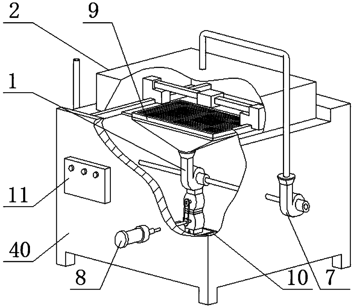
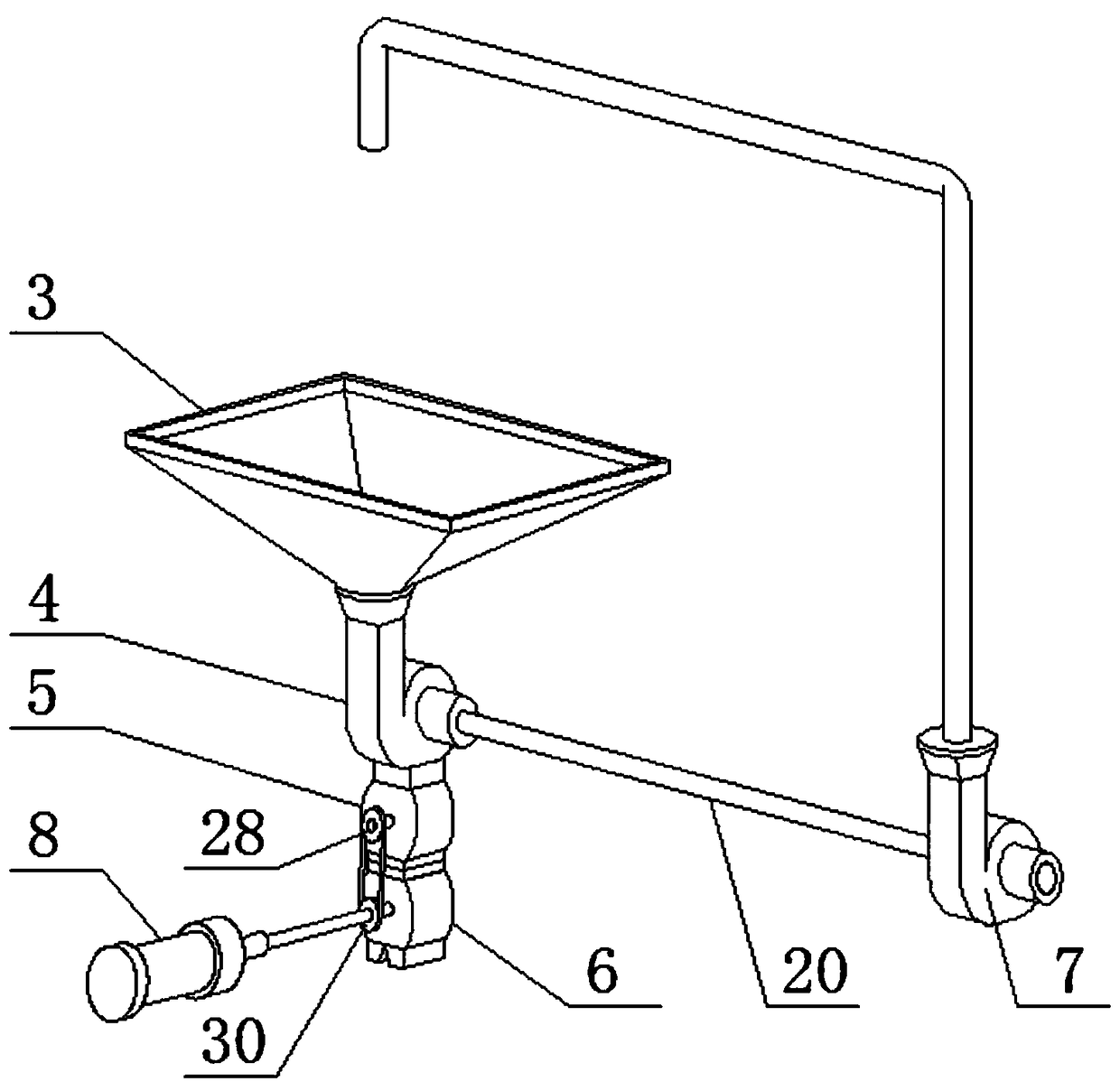
[0029] Examples, see Figure 1-7 , the present invention provides a technical solution:

[0030] A turbocharged dust removal and noise reduction device for a laser cutting machine, comprising a dust removal and noise reduction system 1, a laser cutting machine body 40 and a sealing cover 2 sleeved on the laser cutting machine body 40, the dust removal and noise reduction system 1 passes through a pipeline Connected with the sealing cover 2, the dust removal and noise reduction system 1 includes a shroud 3, a main turbine group 4, a special wind blocker 5, an electromagnetic discharger 6, a secondary turbine group 7, a motor 8, a waste box 10 and a control box 11. The top of the shroud 3 is fixed on the bottom of the support grid 9 on the laser cutting machine body 40, and the main turbine group 4, the special wind choke 5 and the electromagnetic discharger 6 are arranged in sequence from top to bottom In the laser cutting machine body 40, the wind deflector 3, the main turbin...

Embodiment approach

[0032]As a preferred embodiment of the present invention, the first sealing roller 24 includes a bracket 31 and a roller 32, and the roller 32 is provided with rubber.

[0033] As a preferred embodiment of the present invention, the discharge impeller 26 is provided with anchor blades 33 .

[0034] As a preferred embodiment of the present invention, the top of the discharger housing is provided with an eccentric feed pipe 46, and the bottom of the discharger housing is provided with a non-metallic discharge short pipe 34 and a metal discharge short pipe. Pipe 35, waste box 1 36 and waste box 2 37 are arranged on the waste box 10.

[0035] As a preferred embodiment of the present invention, a scraper 38 is provided inside the short metal discharge pipe 35 .

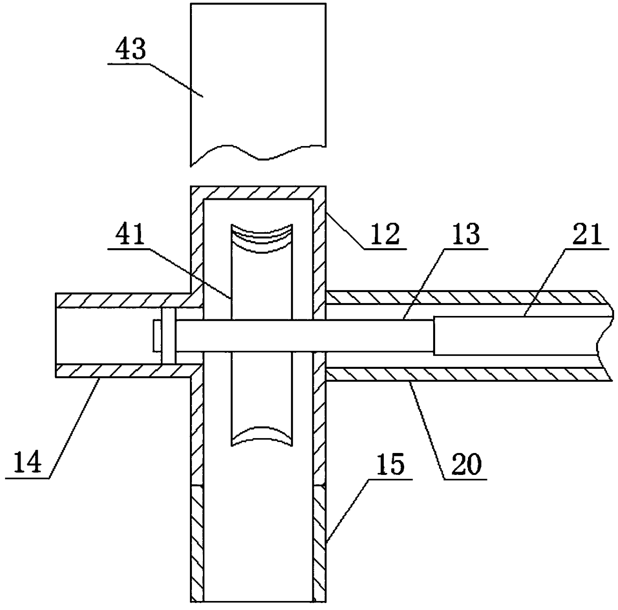
[0036] As a preferred embodiment of the present invention, the electromagnetic drum 22 includes a drum and a coil 39 .

[0037] As a preferred embodiment of the present invention, the first sealing roller 24 and the seco...


PUM


Abstract

The invention relates to the technical field of laser cutting environment-friendly machinery. A dust removal and noise reduction system, a laser cutting machine body and a seal cover are included, andthe laser cutting machine body is sleeved with the seal cover. The dust removal and noise reduction system is connected to the seal cover through a pipeline and comprises a fairing, a main turbine set, a special choke, an electromagnetic discharge device, an auxiliary turbine set, a motor, a waste box and a control box. The top of the fairing is fixed to the bottom of a support grid plate of thelaser cutting machine body. The main turbine set, the special choke and the electromagnetic discharge device are arranged in the laser cutting machine body sequentially from top to bottom. The fairing, the main turbine set, the special choke and the electromagnetic discharge device are fixedly connected through bolts. The waste box is fixed to the bottom of the inner side of the laser cutting machine body and corresponds to the electromagnetic discharge device. The auxiliary turbine set is fixed to the side wall of the laser cutting machine body. The equipment is low in energy consumption, simple to operate, small in noise and free of pollution, and generalization is facilitated.

Description

technical field [0001] The invention is a turbocharged dust removal and noise reduction device for a laser cutting machine, which belongs to the technical field of laser cutting environmental protection machinery. Background technique [0002] In the field of metal cutting machinery, laser cutting machines have become the mainstream production machinery. In terms of cutting, they not only have high processing precision but also high production efficiency. Metal support member, laser gun group, auxiliary air supply system and control part. During the production process, the laser gun group moves vertically and laterally to complete the shape cutting of the metal on the metal support member. The laser gun group irradiates the laser beam The energy released on the surface of the workpiece melts the target position at a high temperature, and the molten metal liquid phase is blown away from the workpiece by means of the blowing system to complete the cutting effect. [0003] How...

Claims


Application Information

Patent Timeline
Patent Type & Authority Applications(China)
IPC IPC(8): B23K26/08B23K26/142B23K26/38F01D15/08B23K101/00
CPCB23K26/0876B23K26/38B23K26/142F01D15/08
Inventor 李朋
Owner 赣州市畅达电梯销售有限公司
Why Eureka
Try Eureka