A garden sewage treatment device
A sewage treatment device and garden technology, which is applied in water/sewage multi-stage treatment, water/sludge/sewage treatment, multi-stage water treatment, etc. It can solve the problem that the sewage treatment effect is not ideal, the filter is easy to block, and the efficiency of sewage treatment is affected. and other problems, to achieve the effect of facilitating breeding, reducing labor intensity and preventing overall blockage
- Summary
- Abstract
- Description
- Claims
- Application Information
AI Technical Summary
Problems solved by technology
Method used
Image
Examples
specific Embodiment approach 1
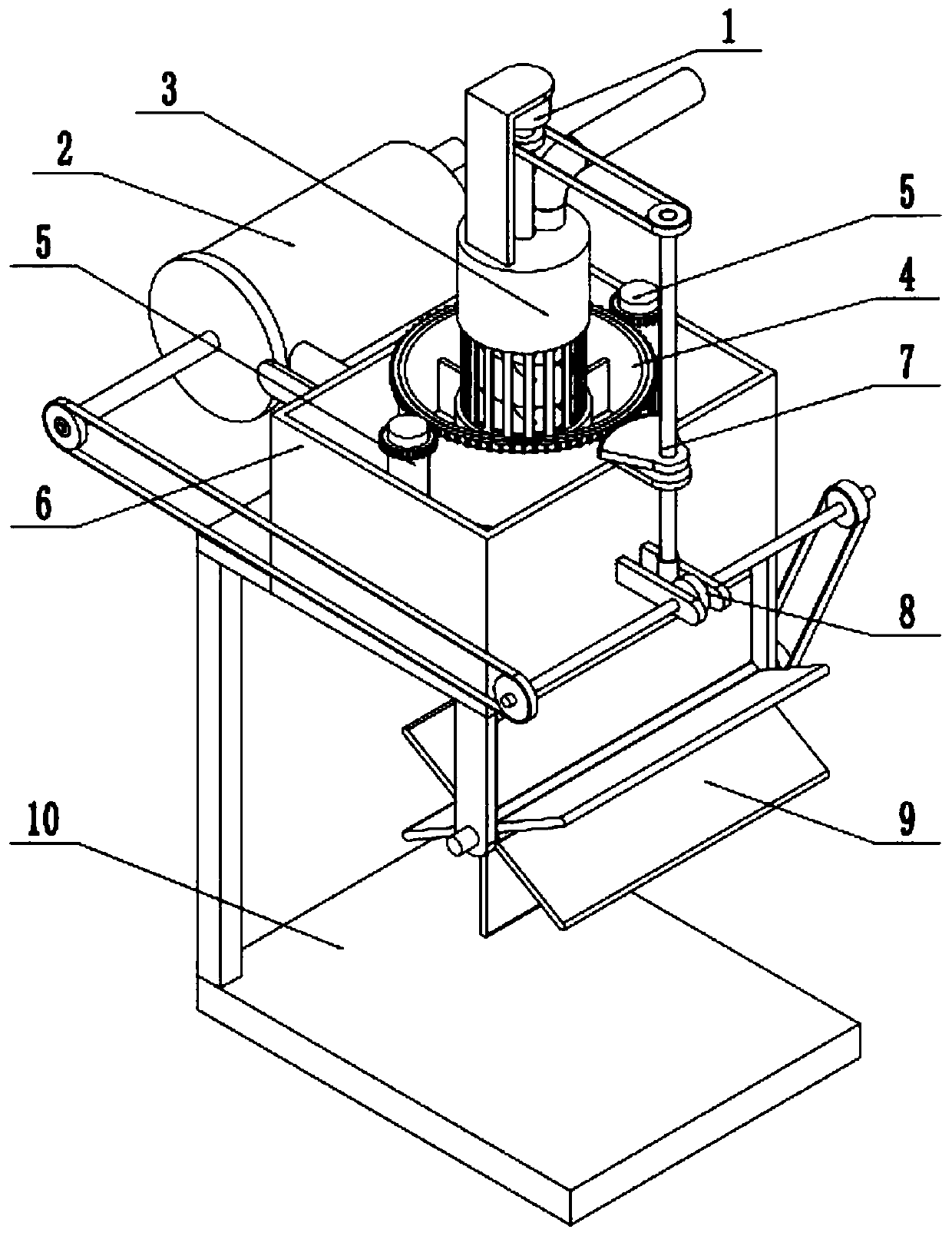
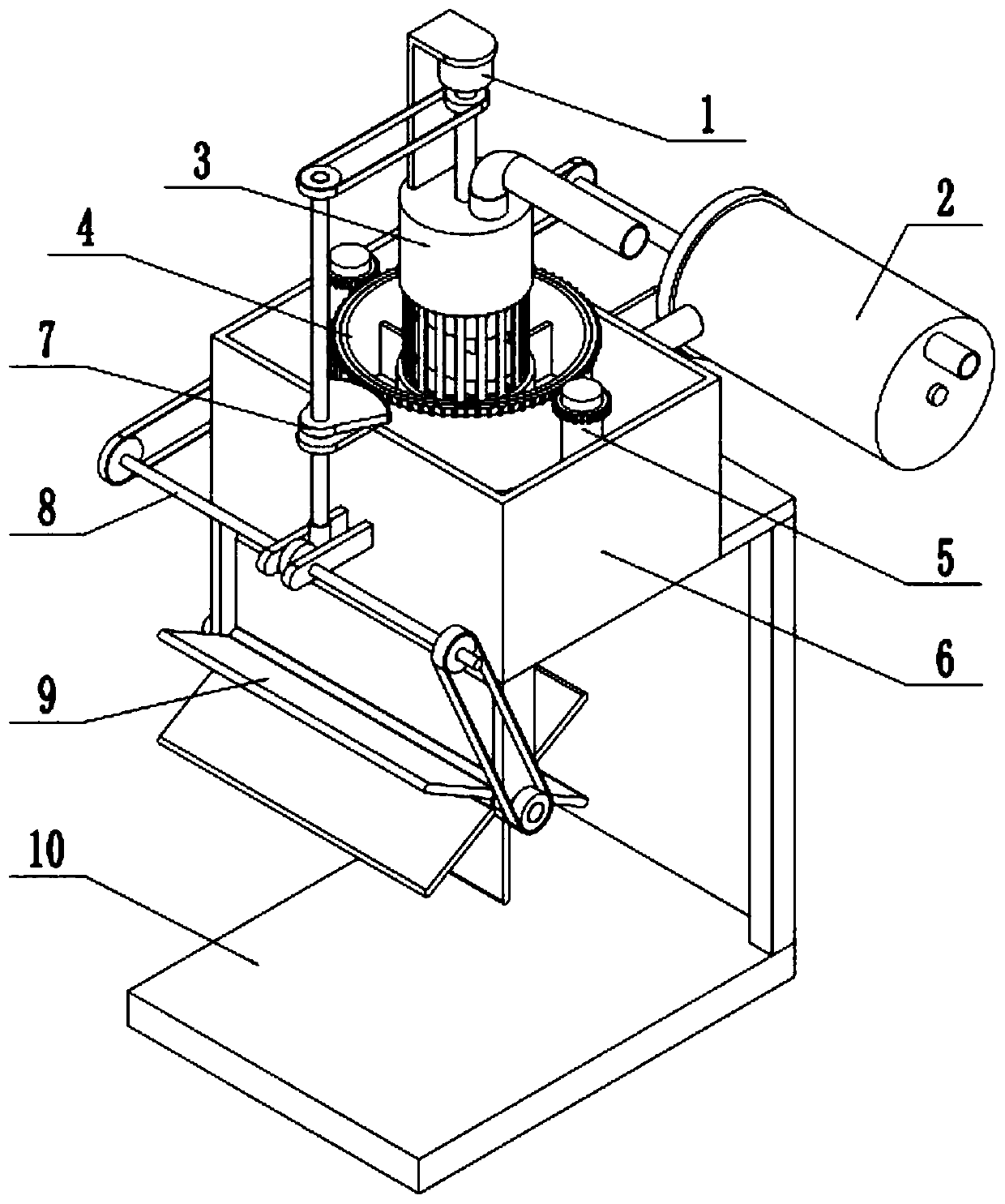
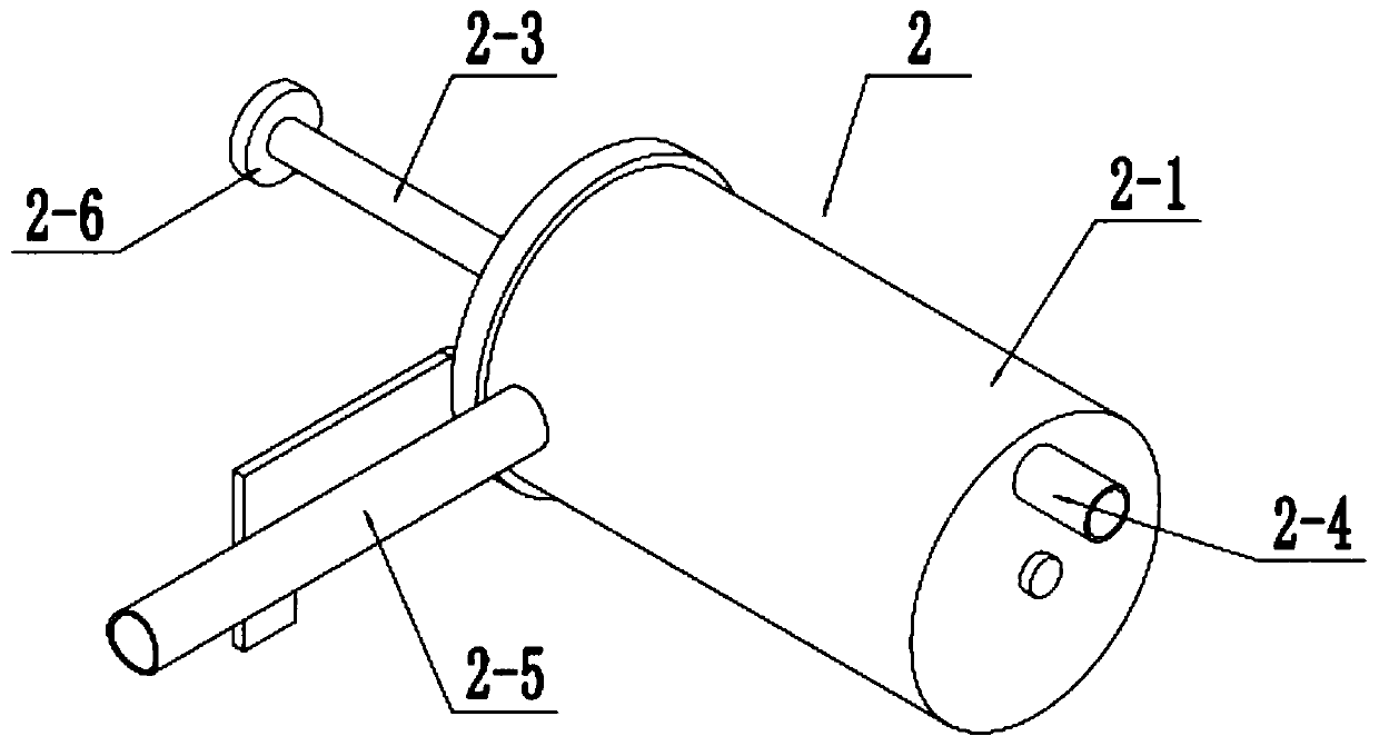
[0030] Such as Figure 1-10 As shown, a garden sewage treatment device includes a driving motor 1, a water inlet crushing cylinder 2, an initial filter and miscellaneous discharge cylinder 3, an intermediate filter cylinder 4, a rear filter cylinder 5, a filter box 6, a linkage wheel assembly 7, and a transmission wheel assembly 8. The water wheel aeration assembly 9 and the support frame 10, the bottom end of the primary filter miscellaneous cylinder 3 is fixedly connected to the middle of the bottom end of the filter box 6, and the filter box 6 is fixedly connected to the support frame 10; the primary filter row The miscellaneous cylinder 3 is connected and communicated with the water inlet crushing cylinder 2, and the water inlet crushing cylinder 2 is fixedly connected to the support frame 10; the middle filter cartridge 4 is rotatably fitted in the filter box 6, and the inner side of the middle filter cartridge 4 is fixedly connected to the primary filter There are two re...
specific Embodiment approach 2
[0033] Such as Figure 1-10 As shown, the primary filter cartridge 3 includes a rotating shaft 3-1, a spiral body 3-2, a driving pulley 3-3, a discharge pipe 3-4 and a primary filter cartridge with a primary filter hole at the middle end of the cylinder surface Body 3-5; the top of the rotating shaft 3-1 is fixedly connected to the output shaft of the drive motor 1; the two ends of the rotating shaft 3-1 are respectively rotated and connected to the top and bottom of the primary filter cartridge body 3-5 Above; the rotating shaft 3-1 is fixedly connected with the driving pulley 3-3 and the spiral body 3-2, the driving pulley 3-3 is located at the upper end of the primary filter cartridge body 3-5, and the spiral body 3-2 is connected in rotation and fits in the primary The inside of the filter cartridge body 3-5; the top of the primary filter cartridge body 3-5 is fixedly connected and communicated with the miscellaneous discharge pipe 3-4; the bottom end of the primary filter...
specific Embodiment approach 3
[0035] Such as Figure 1-10 As shown, the interlocking wheel assembly 7 includes a driven pulley 7-1, an interlocking shaft 7-2, a horizontal frame plate 7-3, an incomplete gear 7-4 and a worm 7-5; the driving pulley 3-3 The driven pulley 7-1 is connected by belt transmission; the driven pulley 7-1 is fixedly connected to the upper end of the linkage shaft 7-2, and the middle end of the linkage shaft 7-2 is fixedly connected to the incomplete gear 7-4; the linkage shaft 7 -2 is connected to the horizontal frame plate 7-3 through rotation and fit of the bearing with seat, the connection between the linkage shaft 7-2 and the horizontal frame plate 7-3 is provided with axial positioning, and the horizontal frame plate 7-3 is fixedly connected to the filter box 6; the lower end of the linkage shaft 7-2 is fixedly connected to the worm 7-5; the incomplete gear 7-4 meshes with the middle filter cartridge 4 in transmission connection; the worm 7-5 meshes with the transmission wheel a...
PUM
 Abstract
Description
Claims
Application Information
 - R&D
- Intellectual Property
- Life Sciences
- Materials
- Tech Scout
- Unparalleled Data Quality
- Higher Quality Content
- 60% Fewer Hallucinations
Browse by: Latest US Patents, China's latest patents, Technical Efficacy Thesaurus, Application Domain, Technology Topic, Popular Technical Reports.
© 2025 PatSnap. All rights reserved.Legal|Privacy policy|Modern Slavery Act Transparency Statement|Sitemap|About US| Contact US: help@patsnap.com


