A novel needle-free electrospinning device and spinning method thereof

An electrospinning and spinning technology, which is applied in the field of new needle-free electrospinning devices, can solve problems affecting the production stability, discharge, and safety hazards of nanofibers, and achieve fine fiber diameter, long range, and high uniformity. Effect

Active Publication Date: 2020-07-10
江苏纳纤新材料科技有限公司
View PDF7 Cites 0 Cited by
  • Summary
  • Abstract
  • Description
  • Claims
  • Application Information

AI Technical Summary

Problems solved by technology

Thus affecting the stability of nanofiber production
At the same time, the above electrospinning devices all require a higher voltage to ensure a larger electric field strength, but high voltage is easy to cause discharge, and there is a huge potential safety hazard in the actual production process

Method used


Image

  • A novel needle-free electrospinning device and spinning method thereof
  • A novel needle-free electrospinning device and spinning method thereof
  • A novel needle-free electrospinning device and spinning method thereof

Examples


Embodiment 1

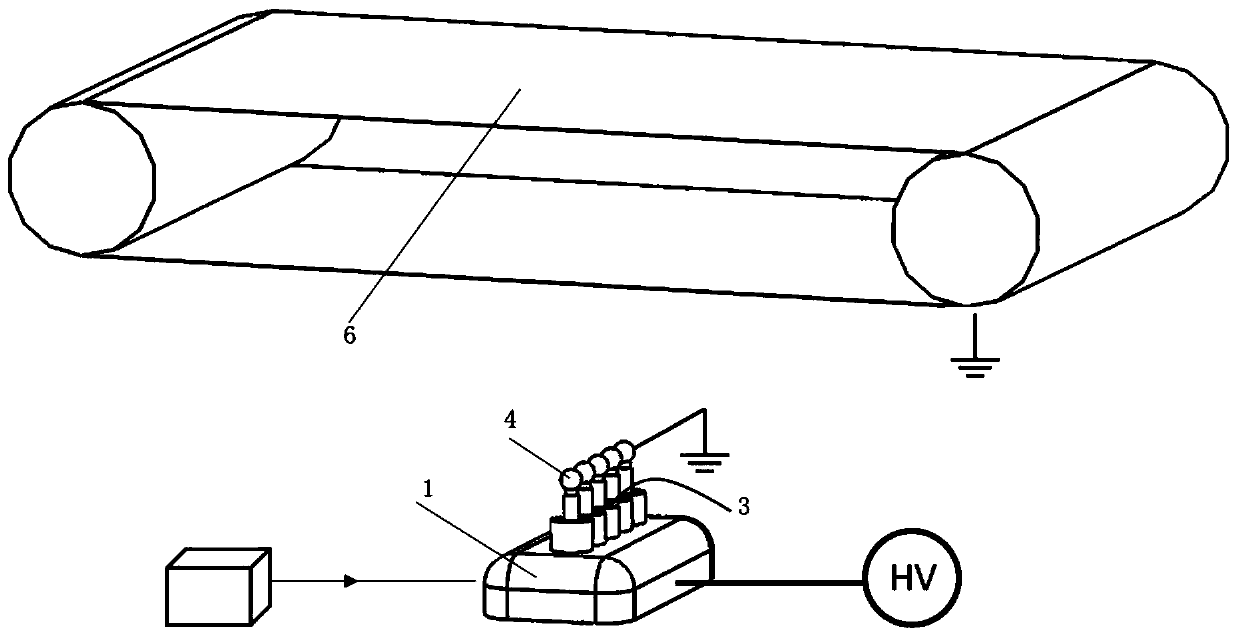
[0130] The electrospinning device used in Example 1 of the present invention is as figure 1 shown. The electrostatic spinning device includes: a spinning solution chamber, a spinning slit, an air flow channel, an intermediate electrode, and a collecting electrode plate. The collecting electrode plate is driven to rotate by a driving device, for example, a motor drives the collecting electrode plate to rotate at a speed of 40 rpm. The ground electrode of the intermediate electrode voltage is connected to induce the production of nanofibers; the collecting electrode plate is connected to the ground electrode and used to receive the produced nanofibers. The distance between the spinning slit and the collecting electrode plate is 200 mm, the distance between the spinning slit and the intermediate electrode is 100 mm, the diameter of the gas flow channel is 20 mm, and the flow rate of the gas in the gas flow channel is 20 m / s.

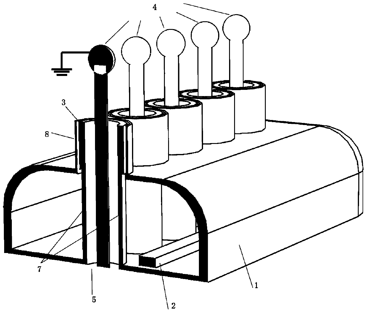
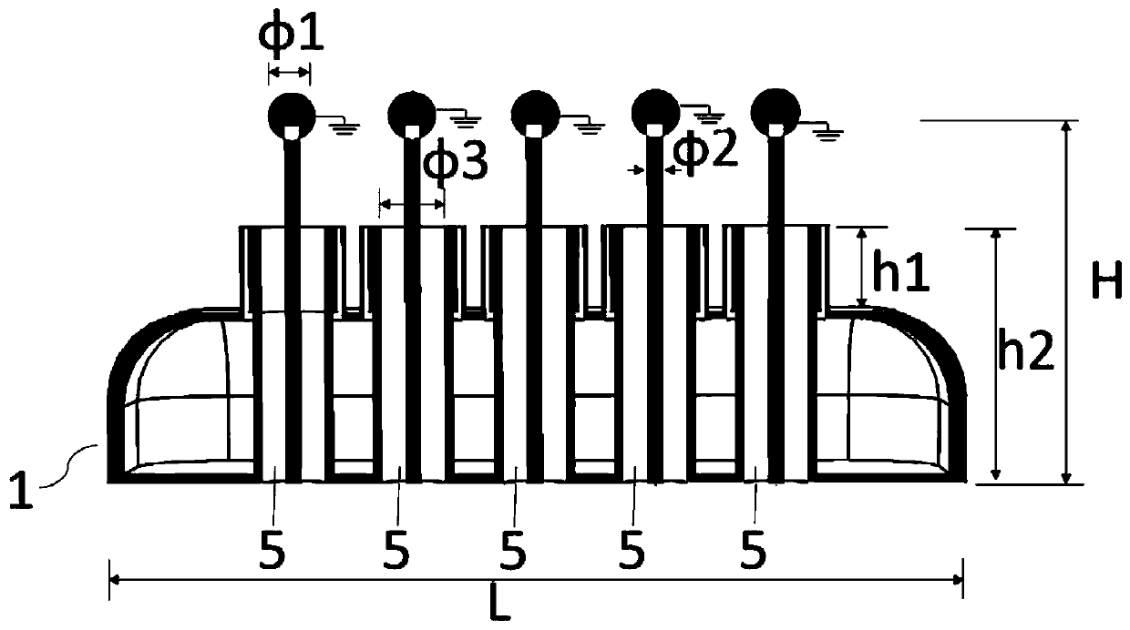
[0131] figure 2 and 3 shown as figure 1 A more ...

Embodiment 2

[0137] The spinning device reference used in this embodiment figure 1 , the intermediate electrode shown as Figure 10 Shown, a cylindrical interposer. The diameter φ4 of the intermediate electrode was 15 mm, and the height h3 of the intermediate electrode was 10 mm. The distance between the intermediate electrode and the slit is 50 mm. The specific shape of the spinning slit is rhombus, such as Figure 14 As shown, the diagonal length l1 of the rhombus is 80mm, the distance between the centers of the rhombus is 100mm, and the internal angles of the rhombus are all 90°. The distance between the spinning slot and the fiber collecting electrode was 200 mm. The diameter of the gas flow channel is 25mm, and the flow velocity of the gas is 25m / s. The slit is made of polypropylene plastic. All the other test parameters are the same as in Example 1.

[0138] For experimental purposes, the nanofibers were formed using a polymer solution produced by Sigma-Aldrich with a viscosit...

Embodiment 3

[0141] The spinning device reference used in this embodiment figure 1 , the slit spinneret shown in the figure is as Figure 15 As shown, it is a rectangular closed linear spinning head. The length L3 of the rectangle is 50 mm, the width l3 of the rectangle is 50 mm, and the distance d4 between the centers of each rectangle is 50 mm. The width d5 ​​of the slit is 2 mm. The distance between the spinning slot and the fiber collecting electrode was 180 mm. The intermediate electrode is a cone, such as Figure 11 As shown, the diameter φ5 of the bottom surface of the cone is 20 mm, the height h4 is 10 mm, and the distance between the intermediate electrode and the slit is 60 mm. The flow velocity of the gas in the gas flow channel is 20m / s. The material of the slit is aluminum. All the other test parameters are the same as in Example 1.

[0142] For experimental purposes, the nanofibers were formed using a polymer solution produced by Sigma-Aldrich with a viscosity of 1100 ...


PUM

PropertyMeasurementUnit
widthaaaaaaaaaa
lengthaaaaaaaaaa
heightaaaaaaaaaa

Abstract

The invention relates to a novel needleless electrospinning device and a spinning method thereof. The novel needleless electrospinning device includes a spinning liquid storage unit, a spinning forming unit and a spinning collecting unit, wherein the spinning forming unit includes a spinning liquid cavity, a charged electrode, a spinning slit, an intermediate electrode and an air flow passage, thecollecting unit includes a collecting electrode board, a first electrostatic field is formed between the charged electrode and the collecting electrode board, a second electrostatic field is formed between the charged electrode and the intermediate electrode, the spun fiber is ejected by the spinning solution in the spinning solution cavity through the spinning slit under the action of the secondelectrostatic field, and the spun fiber is collected to the collecting electrode board under the guide action of the air flow passage and the action of the first electric field. The needleless electrospinning device is advantaged in that electrospinning having properties of high uniformity, more yield, longer range and finer fiber diameters can be provided.

Description

technical field [0001] The invention belongs to the field of electrostatic spinning, and in particular relates to a novel needle-free electrostatic spinning device and a spinning method thereof. Background technique [0002] Nanofibers generally refer to ultrafine fibers with a diameter of less than 1000 nm. Compared with ordinary fibers, nanofibers have the advantages of large specific surface area and high porosity, and have broad application prospects in many fields. Electrospinning technology is a commonly used technology for preparing nanofibers, which has a wide range of applications, simple operation and controllable process. The basic principle of electrospinning technology is that polymer droplets placed in a high-voltage electrostatic field will form a Taylor cone. When the electric field force is large enough, the droplets can overcome the surface tension and eject from the tip of the Taylor cone to form a jet. Under the action of field force, viscous resistance...

Claims


Application Information

Patent Timeline
Patent Type & Authority Patents(China)
IPC IPC(8): D01D5/00
CPCD01D5/0007D01D5/0061D01D5/0069D01D5/0076D01D5/0092
Inventor 林童颜贵龙牛海涛
Owner 江苏纳纤新材料科技有限公司
Why Eureka
Try Eureka