Downward drilling plugging-while-drilling type slag discharging device and method

A technology while drilling, drill pipe, applied in earth-moving drilling, sealing/packing, wellbore/well components, etc., can solve the problem of difficulty in reaching slag discharge pressure, inability to guarantee slag discharge power, and slag discharge power steep drop, etc. problem, to achieve the effect of low input cost, good economic and social benefits, and stable slag discharge power

Pending Publication Date: 2019-01-15
HENAN POLYTECHNIC UNIV
View PDF9 Cites 4 Cited by
  • Summary
  • Abstract
  • Description
  • Claims
  • Application Information

AI Technical Summary

Problems solved by technology

For the drilling construction with small diameter and large depth in the downward direction, high-pressure water is easily affected by the drilling depth. As the drilling depth increases, the hydraulic gradient gradually decreases, and it is difficult to achieve the ideal slag discharge pressure. The spiral slag discharge method is easily affected by the integrity of the hole wall, and the slag discharge power drops sharply in the collapsed hole area, which can easily lead to hole blocking, drill sticking, drill sticking, etc., so that stable and effective slag discharge power cannot be guaranteed. In addition, the two This method of slag discharge will also cause serious air pollution

Method used


Image

  • Downward drilling plugging-while-drilling type slag discharging device and method
  • Downward drilling plugging-while-drilling type slag discharging device and method

Examples


Embodiment Construction

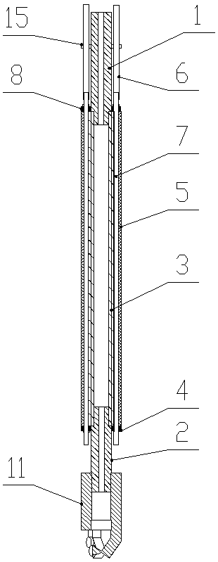
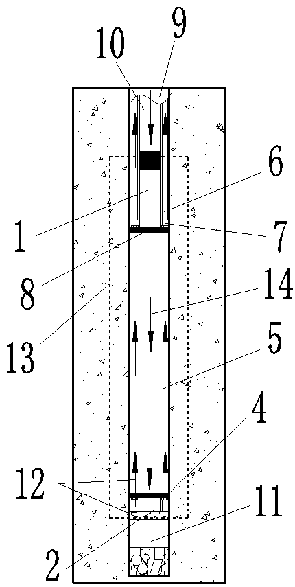
[0025] As pictured and figure 2 As shown, the down-drilling plugging type slag discharge device of the present invention includes an upper hollow connecting rod 1, a lower hollow connecting rod 2, a sealed bearing 3, a sealing rubber ring 5, and an upper slag discharging device arranged vertically. Conduit 6 and lower slag discharge conduit 7;

[0026] The lower end of the upper hollow connecting rod 1 extends into and is threaded into the upper port of the inner ring of the sealed bearing 3, and the upper end of the lower hollow connecting rod 2 extends into and is threaded into the lower port of the inner ring of the sealed bearing 3 to seal the rubber ring 5 sets are arranged on the outer ring of the sealed bearing 3, and the outer ring of the sealed bearing 3 is provided with two inner semicircular long grooves which are transparent up and down along the axial direction. The transparent outer semicircular long groove, two inner semicircular long grooves and two outer sem...


PUM


Abstract

A downward drilling plugging-while-drilling type slag discharging device includes an upper hollow connecting rod, a lower hollow connecting rod, a sealing bearing, a sealing rubber ring, upper slag discharging ducts and lower slag discharging ducts which are all vertically connected. The upper hollow connecting rod and the lower hollow connecting rod are connected respectively with an upper port and a lower port of the bearing inner ring. The sealing rubber ring is arranged on the outer ring of the sealing bearing. Both the number of the upper slag discharging ducts and the number of the lowerslag discharging ducts are two. The two lower slag discharging ducts are assembled between the sealing rubber ring and the outer ring of the sealing bearing. The upper ends of the two lower slag discharging ducts are coaxially connected with the lower ends of the two upper slag discharging ducts correspondingly. The invention further discloses a slag discharging method of the downward drilling plugging-while-drilling type slag discharging device. According to the invention, the structure is compact, the operation is convenient, the construction method is simple, the method can ensure effective and stable slag discharge power, improve the pore-forming quality for small-diameter and large depth drilling and slag discharging effect and reduce the air pollution, and the method is innovative in small-diameter and deep drilling and slag discharging.

Description

technical field [0001] The invention belongs to the technical field of roadway (tunnel) support, and in particular relates to a downhole drilling plugging type slag discharge device and method. Background technique [0002] Drilling in coal and rock mass is an important manifestation of coal and rock cutting. According to engineering needs, the depth and direction of drilling will be different. During the construction of mine support and rock mass blasting, it is often necessary to drill holes with a depth of several meters to tens of meters and different orientations. At this time, the discharge of cuttings generated by drilling is a key factor affecting drilling efficiency. At present, the slag discharge methods in the drilling construction process at home and abroad mainly include: high-pressure water slag discharge, high-pressure air slag discharge and mechanical spiral slag discharge. However, the above slag removal methods are mainly applicable to boreholes with large...

Claims


Application Information

Patent Timeline
Patent Type & Authority Applications(China)
IPC IPC(8): E21B33/12E21B31/00
CPCE21B31/00E21B33/12
Inventor 刘少伟付孟雄刘伟杨云飞王永峰石国文尹文怀李剑侠王颖清
Owner HENAN POLYTECHNIC UNIV
Why Eureka
Try Eureka