Mechanical liquid continuous reversing device

A reversing device, a mechanical technology, used in mechanical equipment, parts of pumping devices for elastic fluids, liquid fuel engines, etc. High commutation frequency problem

Active Publication Date: 2019-01-15
SHANDONG QINGGENG ELECTRIC CO LTD
View PDF5 Cites 3 Cited by
  • Summary
  • Abstract
  • Description
  • Claims
  • Application Information

AI Technical Summary

Problems solved by technology

However, a major disadvantage of the liquid piston mechanical device is that only a reversing valve can be used for the reversing of the liquid movement, and the reversing valve is mainly a solenoid valve or an electric valve. , the whole operation is intermittent or pulse type. This intermittent and pulse type commutation makes the liquid unable to flow continuously, thus affecting the performance of mechanical structures such as air c

Method used


Image

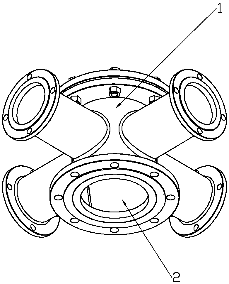
  • Mechanical liquid continuous reversing device
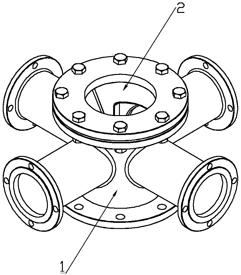
  • Mechanical liquid continuous reversing device
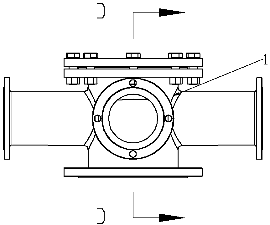
  • Mechanical liquid continuous reversing device

Examples


Embodiment 1

[0029] The structure of the rotor of the present invention is as Figure 5-Figure 8 , Figure 9-Figure 12 and Figure 13-Figure 16 These structures are shown as different embodiments of the rotor 2 . The basic structure of rotor 2 is as follows Figure 13-Figure 16 As shown, the rotor is a cylinder. There are three implementations of the rotor, and the present invention is not limited to these three implementations. Embodiment 1: a chamber is provided on the inner wall of the rotor 2, two through holes are provided on the peripheral wall of the rotor 2, a partition 3 is arranged in the chamber of the rotor, and the partition 3 divides the chamber of the rotor 2 into two independent small chambers, namely : the first independent small chamber 34 , the second independent small chamber 35 . Usually, the volumes of the two independent small chambers are equal, and in special cases, different volumes of the independent small chambers can be set according to actual needs. Each...


PUM


Abstract

The invention relates to a mechanical liquid continuous reversing device, which comprises a stator, wherein the circumferential wall of the stator is provided with a through hole, the inner wall of the stator is matched with a rotor, the circumferential wall of the rotor is provided with two through holes, the rotor is provided with a chamber, the chamber of the rotor is internally provided with an isolation component, the isolation component divides the rotor chamber into two independent small chambers and enables one end of each independent small chamber to be open and the other end of eachindependent small chamber to be closed, the closed ends of the two independent small chambers are respectively located at two ends of the rotor in the height direction, each independent small chambercorresponds to the corresponding through hole on the wall of the rotor, the isolation component is connected with a component driving the rotor to rotate into a whole. The mechanical liquid continuousreversing device can enable a liquid circulating in a pipeline to realize continuous reversing in the case of high-speed motion, thereby enabling the liquid to perform reciprocating motion continuously; or the mechanical liquid continuous reversing device enables a liquid moving in a reciprocating manner continuously in the pipeline to perform circulating motion continuously, thereby converting kinetic energy of the liquid into mechanical energy for external work through a mechanical structure.

Description

technical field [0001] The invention relates to a device using a liquid piston to realize reciprocating motion, in particular to a mechanical liquid continuous reversing device. Background technique [0002] Liquid pistons can be applied to mechanical structures such as air compressors, internal combustion engines, and external combustion engines. The use of liquid pistons in these mechanical devices has the advantages of small friction, simple mechanical structure, low cost, and large piston strokes. The cylinder bore ratio is limited, the sealing performance is good, and its working efficiency is much higher than that of mechanical pistons. However, a major disadvantage of the liquid piston mechanical device is that only a reversing valve can be used for the reversing of the liquid movement, and the reversing valve is mainly a solenoid valve or an electric valve. , the whole operation is intermittent or pulse type. This intermittent and pulse type commutation makes the li...

Claims


Application Information

Patent Timeline
IPC IPC(8): F04B39/00F04B53/14F02F3/00
CPCF02F3/0084F04B39/0011F04B53/14
Inventor 孔祥真
Owner SHANDONG QINGGENG ELECTRIC CO LTD
Why Eureka
Try Eureka