Gearbox

A gearbox and box technology, which is applied to transmission parts, components with teeth, belts/chains/gears, etc. Effect of reaction time, reduced friction loss, simple structure

Pending Publication Date: 2019-01-15
农初杰
View PDF13 Cites 2 Cited by
  • Summary
  • Abstract
  • Description
  • Claims
  • Application Information

AI Technical Summary

Problems solved by technology

[0007] One purpose of the present invention is to provide a gearbox, which solves the problems of complex mechanical structure, large friction, easy damage and non-durability of the current gearbox

Method used


Image

  • Gearbox
  • Gearbox
  • Gearbox

Examples


Embodiment 1

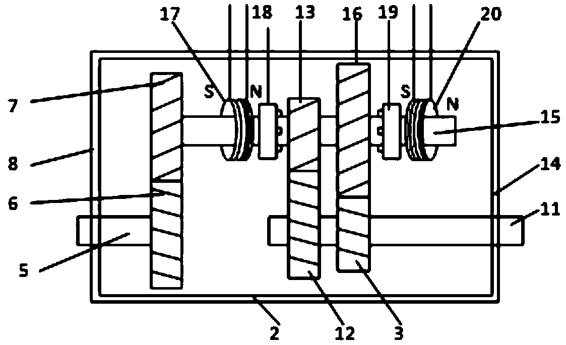
[0034] A gearbox, comprising a gearbox case 2, a power input shaft 5, an intermediate shaft 15 and a power output shaft 11 are pierced inside the gearbox case, and the gears on the intermediate shaft 15 are respectively connected to the gears of the power input shaft 5 and the power The high gear 3 of the output shaft 11 meshes with the low gear 12, the first solenoid 17 and the second solenoid 20 are arranged on the intermediate shaft 15, and the first solenoid 17 and the intermediate shaft pinion 18, between the second solenoid 20 and the intermediate shaft gear 16, a synchronizer is respectively arranged;

[0035] Described gearbox housing 2, power input shaft 5, intermediate shaft 15, power output shaft 11 and all gears are all made of non-ferromagnetic materials, and the synchronizer is made of permanent magnets, consisting of the first solenoid 17 and the second The two solenoids 20 control the synchronizer to move on the intermediate shaft 15 , and a switch circuit for ...

Embodiment 2

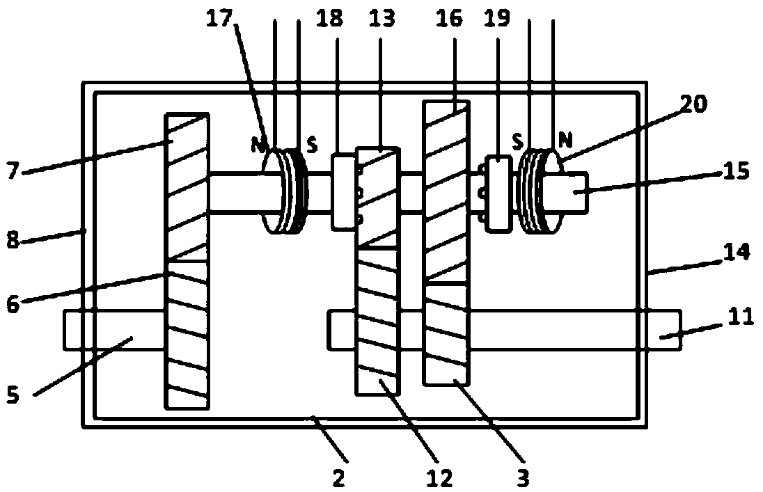
[0039] A gearbox, comprising a gearbox case 2, a power input shaft 5, an intermediate shaft 15 and a power output shaft 11 are pierced inside the gearbox case, and the gears on the intermediate shaft 15 are respectively connected to the gears of the power input shaft 5 and the power The high gear 3 of the output shaft 11 meshes with the low gear 12, the first solenoid 17 and the second solenoid 20 are arranged on the intermediate shaft 15, and the first solenoid 17 and the intermediate shaft pinion 18, between the second solenoid 20 and the intermediate shaft gear 16, a synchronizer is respectively arranged;

[0040] Described gearbox housing 2, power input shaft 5, intermediate shaft 15, power output shaft 11 and all gears are all made of non-ferromagnetic materials, and the synchronizer is made of permanent magnets, consisting of the first solenoid 17 and the second The two solenoids 20 control the synchronizer to move on the intermediate shaft 15 , and a switch circuit for ...

Embodiment 3

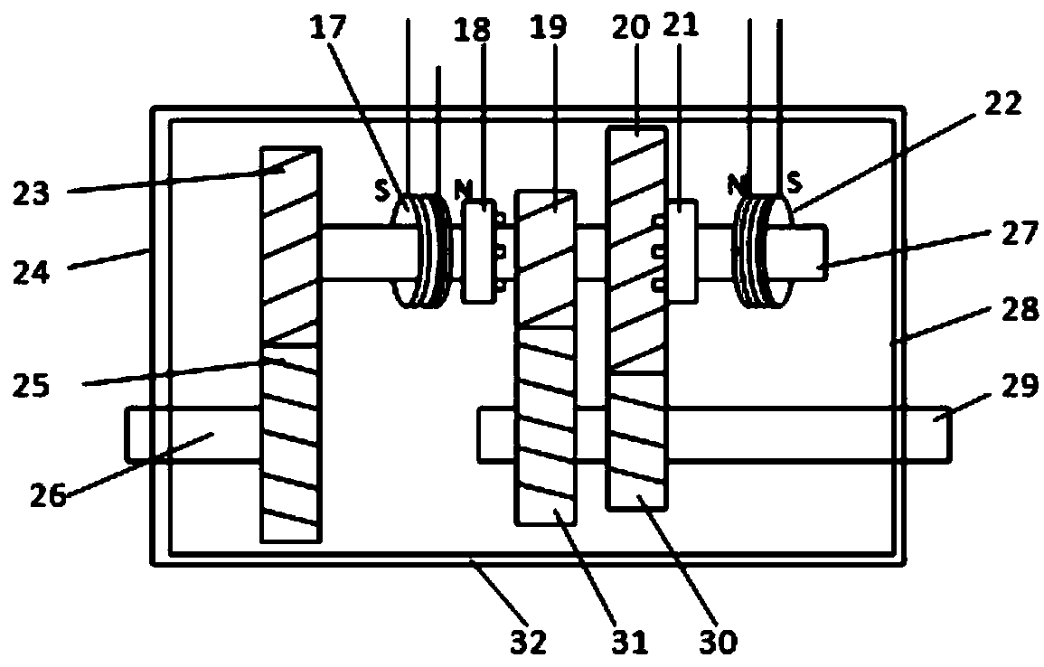
[0047] A gearbox, comprising a gearbox case 2, a power input shaft 5, an intermediate shaft 15 and a power output shaft 11 are pierced inside the gearbox case, and the gears on the intermediate shaft 15 are respectively connected to the gears of the power input shaft 5 and the power The high gear 3 of the output shaft 11 meshes with the low gear 12, the first solenoid 17 and the second solenoid 20 are arranged on the intermediate shaft 15, and the first solenoid 17 and the intermediate shaft pinion 18, between the second solenoid 20 and the intermediate shaft gear 16, a synchronizer is respectively arranged;

[0048] Described gearbox housing 2, power input shaft 5, intermediate shaft 15, power output shaft 11 and all gears are all made of non-ferromagnetic materials, and the synchronizer is made of permanent magnets, consisting of the first solenoid 17 and the second The two solenoids 20 control the synchronizer to move on the intermediate shaft 15 , and a switch circuit for ...


PUM


Abstract

The invention discloses a gearbox. The gearbox comprises a gearbox casing, a power input shaft, an intermediate shaft and a power output shaft are arranged in the gearbox casing in a penetrated way, and each gear on the intermediate shaft is engaged with a gear on the power input shaft or gears on the power output shaft; the intermediate shaft is provided with first and second solenoids, a synchronizer is arranged between the first solenoid and the small gear of the intermediate shaft, and another synchronizer is arranged between the second solenoid and the large gear of the intermediate shaft; the gearbox casing, the power input and output shafts, the intermediate shaft and all the gears are made of non ferromagnetic materials, the synchronizers are made of permanent magnets, and the first and second solenoids control the synchronizers to move on the intermediate shaft; and a switching circuit which controls the current magnitudes and directions of the first and second solenoids is arranged outside the gearbox casing. The gearbox casing solves the problems that a present gearbox is complex in mechanical structure, large in friction force, easy to damage and not durable, and the service life of different components can be prolonged.

Description

technical field [0001] The invention relates to the technical field of automobile braking, and more specifically, the invention relates to an automobile gearbox. Background technique [0002] At present, the torque variation range of the automobile engine is small, which cannot cope with the complex road conditions encountered by the automobile in actual driving, so it is imperative to increase the traction force and driving speed of the automobile. [0003] The production of the gearbox has solved the above-mentioned problems very well. The gearbox can adapt to the frequently changing driving conditions by changing the transmission ratio and expanding the range of torque and speed of the driving wheel. At the same time, the engine works under favorable conditions, with higher power and lower fuel consumption. Moreover, the gearbox can make the car run backwards under the condition that the rotation direction of the engine remains unchanged, and the neutral gear can be used...

Claims


Application Information

Patent Timeline
Patent Type & Authority Applications(China)
IPC IPC(8): F16H57/023F16H61/26
CPCF16H57/023F16H61/26
Inventor 农初杰黄卫军
Owner 农初杰
Why Eureka
Try Eureka