A gps-based high-voltage line inspection device
A high-voltage line and drive device technology, applied in the direction of measurement device, cable installation, overhead line/cable equipment, etc., can solve problems such as damage and unusability, low efficiency, surface damage, etc. Install stable effects
- Summary
- Abstract
- Description
- Claims
- Application Information
AI Technical Summary
Problems solved by technology
Method used
Image
Examples
Embodiment 1
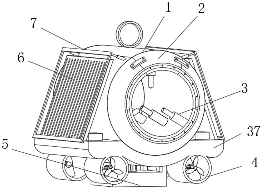
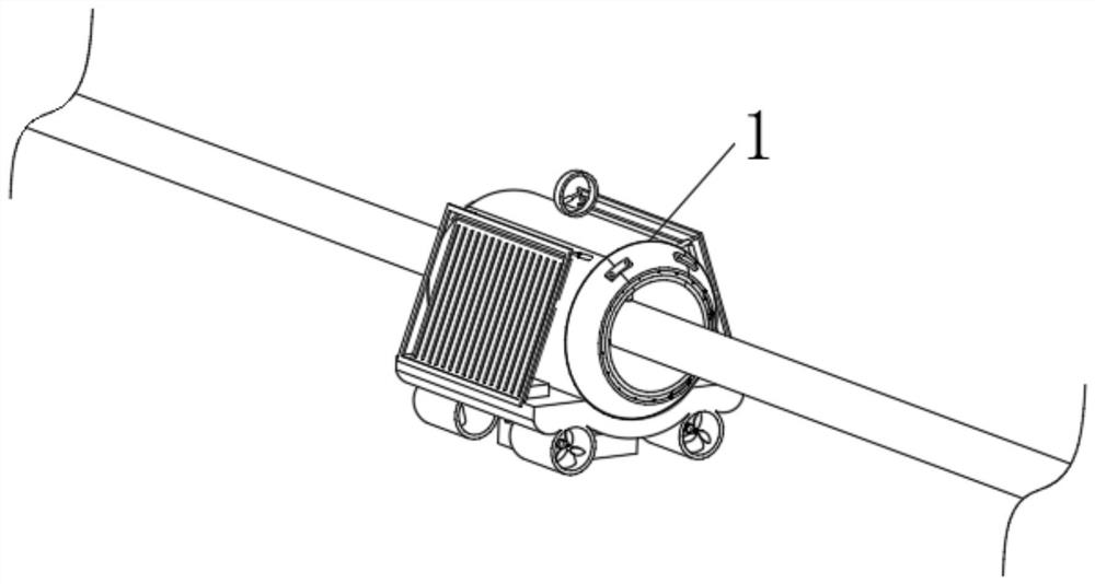
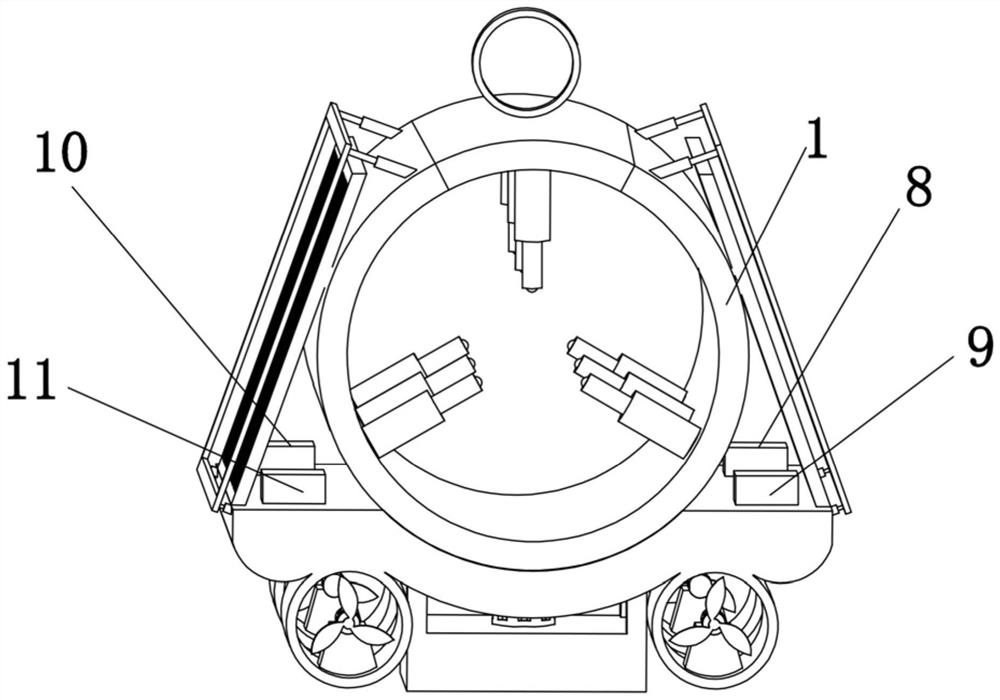
[0062] Embodiment one please refer to Figure 1-3 , a GPS-based high-voltage line inspection device, including a cylinder 1, a snow removal device 2, a clamping device 3, a drive device 4, a weight reduction device 5, a solar panel 6 and a protection device 7, characterized in that: Both ends of the cylinder body 1 are symmetrically fixed with snow removal devices 2, and the cylinder body 1 is provided with clamping devices 3, and there are nine clamping devices 3, and every three are evenly distributed on the cylinder body in a ring. 1, and three rows are equidistantly arranged, the bottom of the cylinder 1 is fixed with a base 37, and the four corners of the bottom of the base 37 are respectively fixed with a driving device 4, and the driving device 4 at one end of the base 37 is connected to the The driving device 4 located at the other end of the base 37 faces oppositely, and the weight reducing device 5 is fixed at the center of the bottom of the base 37, and the solar ce...
Embodiment 2
[0063] Embodiment 2 Please refer to Figure 4 , the snow removal device 2 includes an outer cover 28, an inner cover 29 and a hot blower 30, the outer cover 28 and the inner cover 29 are fixed on the end of the cylinder body 1, and the outer cover 28 is sleeved on the outside of the inner cover 29, the described A heat blower 30 is fixedly connected to the inner cover 29 .
Embodiment 3
[0064] Embodiment three please refer to Figure 5 , 6, the clamping device 3 includes a sliding cylinder 12, an electromagnet plate 13, a first spring 14, a baffle plate 15, a sliding rod 16 and a ball 17, the sliding cylinder 12 is fixed on the inner wall of the cylinder body 1, and the sliding cylinder 12 The inner bottom is fixed with an electromagnet plate 13, one side of the electromagnet plate 13 is fixedly connected to one end of the first spring 14, and the other end of the first spring 14 is fixedly connected to the baffle plate 15, and the baffle plate 15 is connected with the sliding cylinder 12 is slidingly fitted, the side of the baffle plate 15 away from the first spring 14 is fixedly connected to one end of the sliding rod 16, and the sliding rod 16 passes through the sliding tube 12, and the other end of the sliding rod 16 is movably embedded with a ball 17.
PUM
 Abstract
Description
Claims
Application Information
 - R&D
- Intellectual Property
- Life Sciences
- Materials
- Tech Scout
- Unparalleled Data Quality
- Higher Quality Content
- 60% Fewer Hallucinations
Browse by: Latest US Patents, China's latest patents, Technical Efficacy Thesaurus, Application Domain, Technology Topic, Popular Technical Reports.
© 2025 PatSnap. All rights reserved.Legal|Privacy policy|Modern Slavery Act Transparency Statement|Sitemap|About US| Contact US: help@patsnap.com


