Three-dimensional space secondary positioning method based on direct wave inversion

A secondary positioning, three-dimensional space technology, applied in the field of oil and gas exploration seismic data processing, can solve the problems of low recovery rate, affecting production efficiency, slow data acquisition, etc. Effect

Active Publication Date: 2019-01-15
CHINA PETROLEUM & CHEM CORP +1
View PDF4 Cites 5 Cited by
  • Summary
  • Abstract
  • Description
  • Claims
  • Application Information

AI Technical Summary

Problems solved by technology

[0002] The existing relocation methods of the receiver point mainly include the acoustic wave location method and the first arrival wave location method. There are certain limitations in secondary positioning. Acoustic secondary positioning requires expensive equipment, slow data acquisition and low recovery rate, which affects production efficiency. Verification of accuracy
At present, the secondary positioning method of the first arrival is widely used. This method uses the principle of circle intersection, but this principle is based on the algorithm of the plane two-dimensional space. In actual production, the shot point and the receiver point cannot be exactly on the same plane. , this will produce a certain error, which will reduce the accuracy of the calculated coordinates of the geophone point, and this method cannot obtain the water depth of the geophone point
[0003] In the shallow sea and the land-sea transition zone, the geophone sinks into the bottom of the sea by throwing or mechanically laying cables. When it is under the strong impact of currents, tides, and swells, it is difficult for the geophone to be completely fixed on the bottom of the sea, and drifting will occur. The cable cannot realize real-time positioning, causing the actual position of the detector point to be inconsistent with the designed coordinates
If the subsequent seismic data processing is performed on the offset coordinates of the receiver points, the isotropy of the data will be affected, and the resolution of the seismic data and the accuracy of migration homing will be further affected, which will eventually affect the quality of the entire data processing.

Method used


Image

  • Three-dimensional space secondary positioning method based on direct wave inversion
  • Three-dimensional space secondary positioning method based on direct wave inversion
  • Three-dimensional space secondary positioning method based on direct wave inversion

Examples


Embodiment Construction

[0026] In order to make the above and other objects, features and advantages of the present invention more comprehensible, the preferred embodiments are listed below and shown in the accompanying drawings in detail as follows.

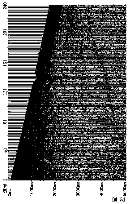
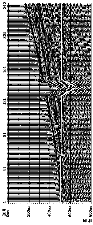
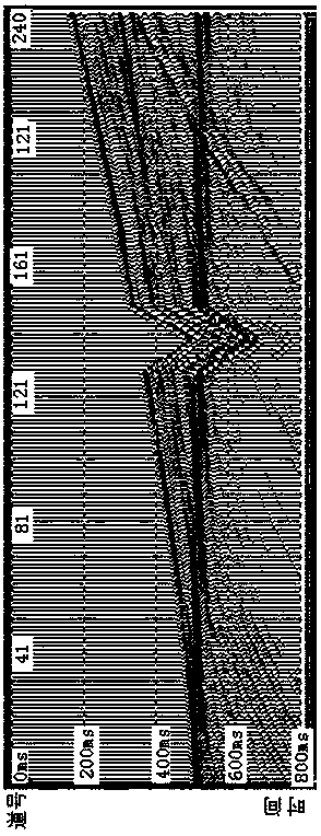
[0027] The direct wave is the wave field in which the seismic wave is directly transmitted from the shot point to the receiver point through the seawater. The direct wave can be manually picked up by a single shot; the speed of the seawater is relatively easy to measure, and it is basically constant in a certain work area. Using the velocity of the direct wave and seawater, the distance from the shot point to the receiver point can be calculated directly. The coordinates of the shot point can be directly measured by the satellite positioning system, so that a spherical surface with the shot point as the center and the distance from the shot point to the receiver point as the radius can be obtained. For a receiver point, use the same method to obtain th...


PUM


Abstract

The invention provides a three-dimensional space secondary positioning method based on direct wave inversion, the method comprises the following steps of: step 1, loading an observation system, and picking up the direct wave; step 2, calculating the actual offset distance; step 3, listing the coordinate equation of the inspection point, and calculating the coordinate equation; step 4, removing theinvalid solution of the coordinate equation; step 5, calculating the secondary positioning coordinates of the inspection point; and step 6, carrying out the coordinate replacement. Compared with theconventional two-dimensional method result, the result of the three-dimensional space secondary positioning method based on the direct wave inversion is more reasonable, more accurate, reliable in effect, simple in flow and parameter setting, high in operation speed and easy to implement.

Description

technical field [0001] The invention relates to the technical field of oil and gas exploration seismic data processing, in particular to a three-dimensional space secondary positioning method based on direct wave inversion. Background technique [0002] The existing relocation methods of the receiver point mainly include the acoustic wave location method and the first arrival wave location method. There are certain limitations in secondary positioning. Acoustic secondary positioning requires expensive equipment, slow data acquisition and low recovery rate, which affects production efficiency. Verification of accuracy. At present, the secondary positioning method of the first arrival is widely used. This method uses the principle of circle intersection, but this principle is based on the algorithm of the plane two-dimensional space. In actual production, the shot point and the receiver point cannot be exactly on the same plane. , this will produce a certain error, which wil...

Claims


Application Information

Patent Timeline
Patent Type & Authority Applications(China)
IPC IPC(8): G01V1/28
CPCG01V1/28
Inventor 李凌云梁鸿贤王常波揭景荣石林光唐中力蔡立新王蓬
Owner CHINA PETROLEUM & CHEM CORP
Why Eureka
Try Eureka