High speed adaptive optical ring spot correction system and method based on machine learning

An adaptive optics, annular spot technology, applied in optics, optical components, instruments, etc., can solve problems such as resolution drop, achieve the effect of high accuracy, solve resolution drop, and the system is simple and easy to operate

Pending Publication Date: 2019-01-15
ZHEJIANG UNIV
View PDF5 Cites 9 Cited by
  • Summary
  • Abstract
  • Description
  • Claims
  • Application Information

AI Technical Summary

Problems solved by technology

[0004] In order to solve the problem of resolution reduction caused by the primary aberration of the optical system and the impact of deep biological sample scattering on the distribution of annular extinction light in the background technology, the present invention provides a high-speed adaptive optical annular spot based on machine learning Calibration systems and methods

Method used


Image

  • High speed adaptive optical ring spot correction system and method based on machine learning
  • High speed adaptive optical ring spot correction system and method based on machine learning
  • High speed adaptive optical ring spot correction system and method based on machine learning

Examples


Embodiment Construction

[0047] The present invention will be further described below with reference to the accompanying drawings and embodiments.

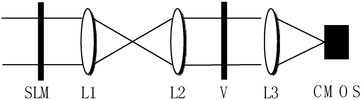
[0048] like figure 1 As shown, the implemented system includes a spatial light modulator SLM, a first lens L1, a second lens L2, a vortex phase plate V, a third lens L3 and a CMOS industrial camera, which are sequentially arranged along the optical path direction. Among them, the spatial light modulator SLM is a reflective type. For the convenience of description and understanding, figure 1 The picture is transmissive. In a specific implementation, the CMOS industrial camera can also be replaced by an EMCCD camera.

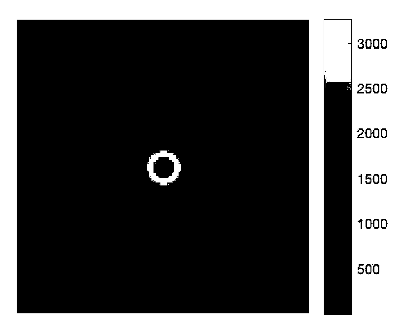
[0049] After the incident parallel light passes through the spatial light modulator SLM, the first lens L1, the second lens L2, the vortex phase plate V, and the third lens L3 in sequence, the annular spot light is detected by the CMOS industrial camera on the focal plane of the system. strong distribution and form an image.

[0050] The ...


PUM


Abstract

The invention discloses a high speed adaptive optical ring spot correction system and method based on machine learning. According to the system and the method, a learning model is established, a mapping relationship between distorted ring spot forms and phase reconstruction coefficients required for correcting deformation is established, a to-be-tested distorted ring spot is input into a trained model, the phase reconstruction coefficient for correcting the distortion can be solved, and further correction phase reconstructed by the phase reconstruction coefficient is loaded to a spatial lightmodulator, so the distortion can be corrected. According to the system and the method, rapid correction can be carried out on ring spot aberration in a stimulated emission depletion (STED) fluorescence microscopy, precision is high, the system is simple and is easy to operate, and the resolution reduction problem resulting from the aberration and scattering generated when sample deep layer imagingis carried out in an STED super-resolution microscopy imaging technology is solved.

Description

technical field [0001] The invention belongs to an adaptive optical wavefront aberration correction method in the field of super-resolution microscopy imaging, and in particular relates to a machine learning-based high-speed method for correcting annular spot aberrations in stimulated emission depletion (STED) fluorescence microscopy. Adaptive optics correction systems and methods to enable super-resolution optical imaging in thick samples. Background technique [0002] Optical microscopy has long been an important tool in biomedical research due to its non-contact and non-invasive advantages. However, since 1873, it has been believed that the resolution limit of the optical microscope is about 200nm, which cannot be used to clearly observe biological structures within 200nm in size. Super-resolution optical imaging is the most significant breakthrough in the field of optical microscopy imaging in this century, breaking the resolution limit of optical microscopy and providi...

Claims


Application Information

Patent Timeline
Patent Type & Authority Applications(China)
IPC IPC(8): G02B21/00G02B27/00G02B27/58
CPCG02B21/0072G02B27/0025G02B27/58
Inventor 斯科龚薇章一叶
Owner ZHEJIANG UNIV
Why Eureka
Try Eureka