A spatial positioning method of tower crane based on machine vision

A space positioning and machine vision technology, applied in the direction of instruments, load hanging components, image data processing, etc., can solve the problems of not being able to fully observe the surrounding environment of the construction site, increasing potential safety hazards, increasing construction costs, etc. , to facilitate calculation, reduce potential safety hazards, and save construction costs

Inactive Publication Date: 2019-01-15
HEFEI UNIV OF TECH
View PDF7 Cites 6 Cited by
  • Summary
  • Abstract
  • Description
  • Claims
  • Application Information

AI Technical Summary

Problems solved by technology

Due to the structural characteristics of the tower crane, there is a visual blind spot, and the operator cannot fully observe all the conditions on the construction site and the surrounding environment.
[0003] In the process of tower crane construction, the cooperation of ground commanders and operators is required to avoid visual blind spots, which not only reduces work efficiency, increases construction costs, but also increases potential safety hazards

Method used


Image

  • A spatial positioning method of tower crane based on machine vision
  • A spatial positioning method of tower crane based on machine vision
  • A spatial positioning method of tower crane based on machine vision

Examples


Embodiment 1

[0041] A machine vision-based tower crane space positioning method, comprising the following steps:

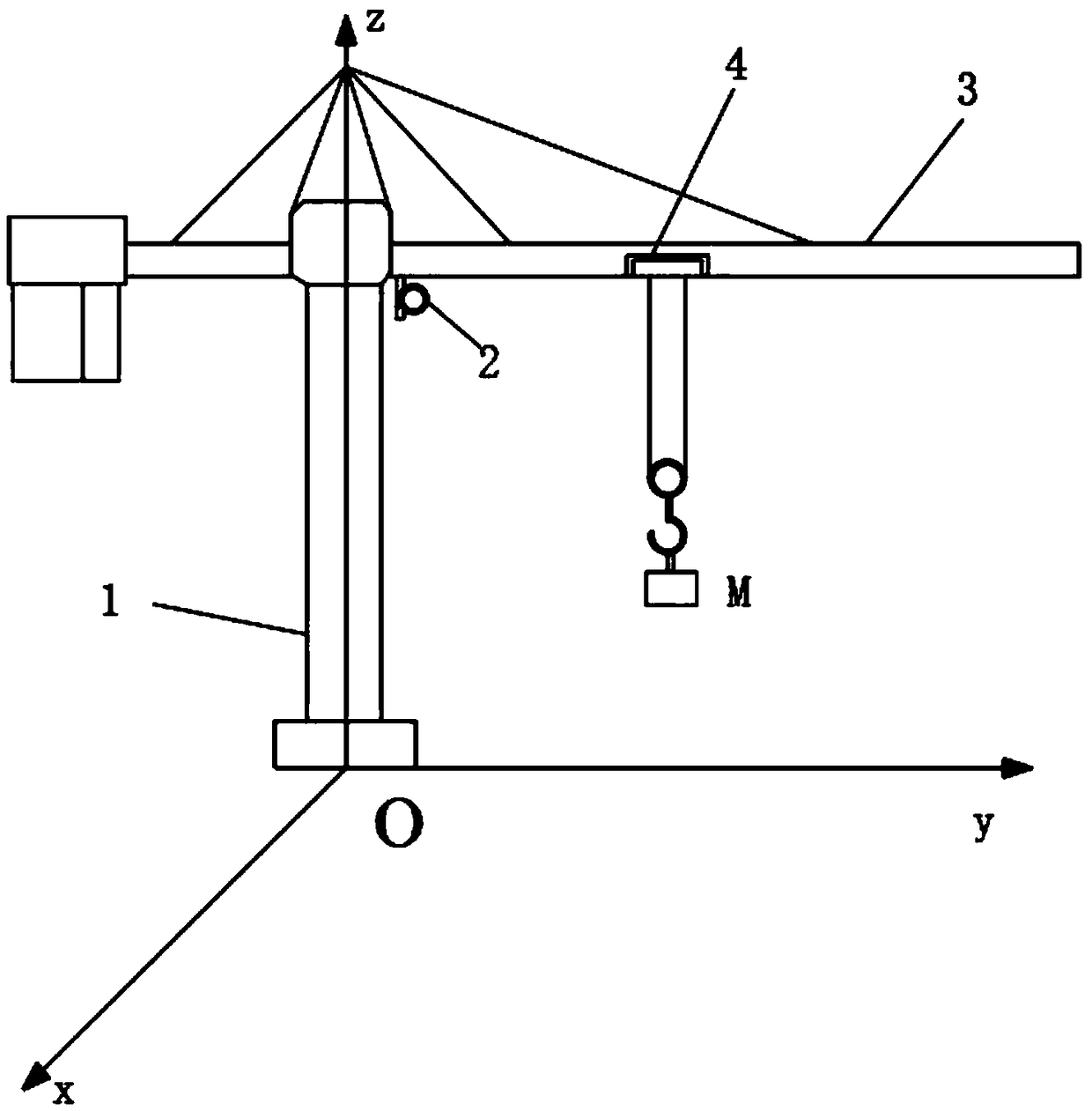
[0042] S10, set up as figure 1 The spatial coordinate system shown.

[0043] S11, the binocular camera 2 used to obtain machine vision captures the image of the heavy object on the tower crane, and the binocular camera 2 transmits the image of the heavy object to the controller; the controller combines the built-in binocular camera SGBM ranging algorithm to obtain the heavy object In the coordinates of the space coordinate system, the spatial positioning of the heavy objects suspended on the tower crane is completed. In this embodiment, the binocular camera 2 is a camera lens with a lens viewing angle of 45 degrees and high resolution. The SGBM ranging algorithm is a stereo matching ranging algorithm. The model of the controller is RK3399.

Embodiment 2

[0045] On the basis of Embodiment 1, the specific steps of establishing a space coordinate system in step S10 are:

[0046] The center of the base at the bottom end of the support frame 1 of the tower crane is the coordinate origin o of the space coordinate system; the projection of the original position of the boom 3 of the tower crane on the ground where the base is located is the y-axis; the y-axis rotates clockwise The radian is the x axis; the support frame 1 is the z axis.

[0047] In this embodiment, the projection of the original position of the boom 3 of the tower crane on the ground where the base is located is the positive semi-axis of the y-axis; the positive semi-axis of the y-axis rotates clockwise The arc is the positive semi-axis of the x-axis; the support frame 1 is the positive semi-axis of the z-axis.

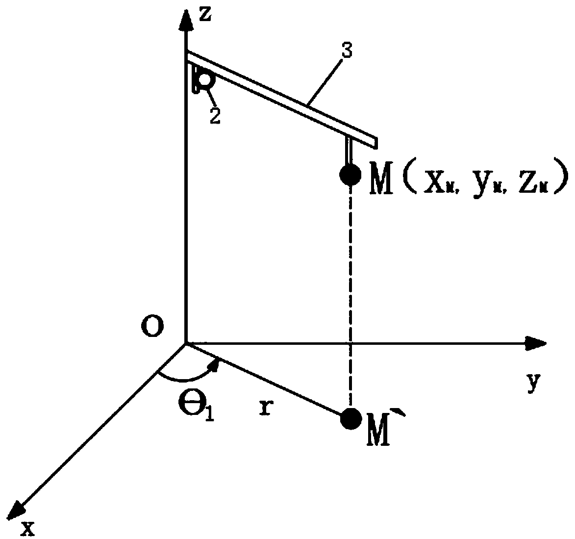
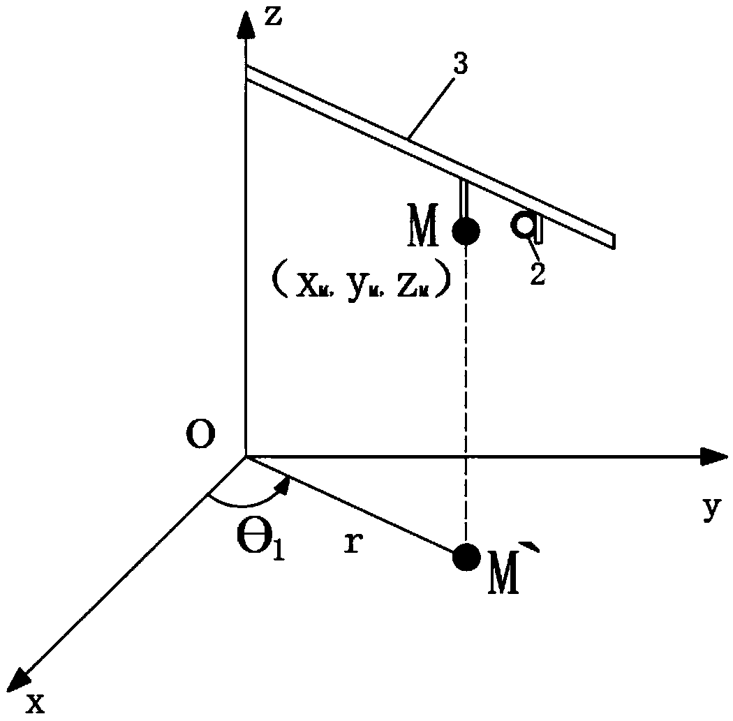
[0048] The specific steps of the position of the positioning weight in step S11 are as follows:

[0049] S111, the boom 3 rotates in the horizontal direc...

Embodiment 3

[0058] On the basis of embodiment 1 and embodiment 2.

[0059] S40, the controller sets the space coordinate system and the coordinates of the heavy object at the M position (x M ,y M ,z M ) and images of heavy objects are transmitted to the display;

[0060] S41, the operator inputs the coordinates of the target position of the heavy object;

[0061] S42, the display transmits the coordinates of the target position of the heavy object to the controller, and the controller calculates the moving path of the heavy object;

[0062] S43. Calculate the rotational angular velocity of the tower crane and the displacement velocity of the tower crane according to the moving path of the heavy object, and locate the moving range of the tower crane.

[0063] The operator obtains the position of the heavy object through the display, and can see the position of the heavy object more intuitively, which facilitates the operation of the tower crane. The controller plans the displacement p...


PUM


Abstract

The invention relates to the technical field of tower crane positioning, in particular to a tower crane spatial positioning method based on machine vision. The spatial positioning method of the towercrane comprises the following steps: establishing a spatial coordinate system; acquiring a weight image captured on the tower crane by a binocular camera of machine vision; transmitting the weight image to a controller by the binocular camera; combined with the built-in SGBM algorithm, the controller obtains the coordinates of the weight in the spatial coordinate system, and completes the spatialpositioning of the weight suspended on the tower crane. The binocular camera replaces the ground commander, can more accurately locate the position of heavy objects, avoids the blind area, and improves the work efficiency. As the cooperation of the ground commander is not required, the construction cost is saved and the potential safety hazard is reduced.

Description

technical field [0001] The invention relates to the technical field of tower crane positioning, in particular to a machine vision-based tower crane space positioning method. Background technique [0002] Tower cranes have been widely used in the field of construction due to their long booms, high heights of support frames, heavy loads that can be hoisted, simple structures, and large coverage areas. The structural characteristics of the tower crane make it have a blind spot, and the operator cannot fully observe all the conditions on the construction site and the surrounding environment. [0003] In the process of tower crane construction, the cooperation of ground commanders and operators is required to avoid visual blind spots, which not only reduces work efficiency, increases construction costs, but also increases potential safety hazards. Contents of the invention [0004] In order to solve the above technical problems, the object of the present invention is to provid...

Claims


Application Information

Patent Timeline
Patent Type & Authority Applications(China)
IPC IPC(8): G06T7/73B66C13/46
CPCB66C13/46G06T7/73G06T2207/20068
Inventor 储昭碧张锐陈波张武松
Owner HEFEI UNIV OF TECH
Why Eureka
Try Eureka