Cement homogenizing equipment with pre-crushing function

A homogenization equipment and pre-crushing technology, which is applied in mixers with rotary stirring devices, mixed material pretreatment, chemical instruments and methods, etc., can solve the problems of screening structure, single stirring function, large space occupation, and equipment energy consumption Advanced problems, to achieve the effect of ingenious and reasonable power connection, ingenious structural design, and prevention of accumulation and blockage

Inactive Publication Date: 2019-01-18
罗永山
View PDF1 Cites 1 Cited by
  • Summary
  • Abstract
  • Description
  • Claims
  • Application Information

AI Technical Summary

Problems solved by technology

[0004] The above scheme does not have a dispersing device, and when the material particles are uneven, it is prone to inverted heap segregation. The sieving structure and stirring function are single, and the homogenization effect is poor. Moreover, the equipment consumes a lot of space and cannot solve the end-heap effect.

Method used


Image

  • Cement homogenizing equipment with pre-crushing function
  • Cement homogenizing equipment with pre-crushing function
  • Cement homogenizing equipment with pre-crushing function

Examples


Embodiment 1

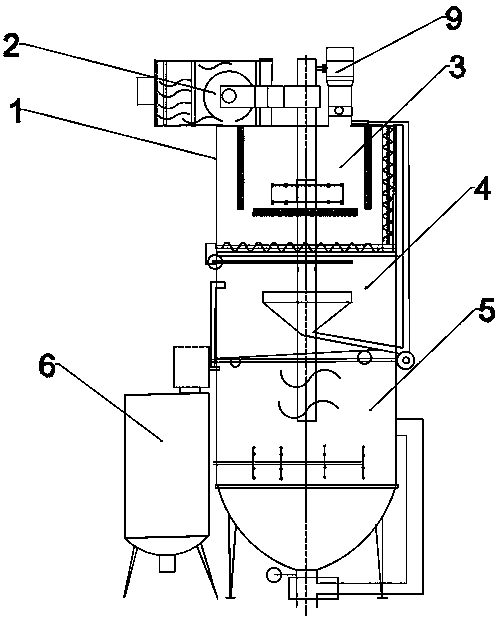
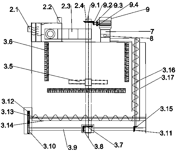
[0032] As shown in the accompanying drawings of the description, a cement homogenization equipment with pre-crushing function includes equipment tank 1, driving mechanism 2, breaking bin 3, screening bin 4, mixing bin 5, auxiliary mechanism 6 and pre-crushing equipment. Crushing mechanism 9; the driving mechanism 2 is fixed on the top of the equipment tank 1 and driven by a water turbine. Both ends of the driving mechanism 2 are connected with a water inlet 2.1 and a water outlet 2.2, and the output of the driving mechanism 2 is connected to the gearbox 2.3, the output of the gearbox 2.3 is connected to the main shaft 2.4; the main shaft 2.4 is fixed in the middle of the equipment tank 1, the upper part of the main shaft 2.4 passes through the gearbox 2.3, and the lower part passes through the breaking bin 3 and the screening bin 4 and mixing discharge bin 5; said breaking up bin 3 is provided with a breaking up cutter head 3.5, a counterattack plate 3.6, a horizontal screw con...

Embodiment 2

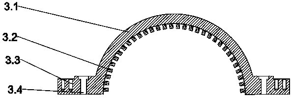
[0040] The structure and principle of the present embodiment 2 are basically the same as that of the embodiment 1, except that the sieve hole 3.61 is provided with a spiked partition 3.63 between the two holes, the bottom of the spiked partition 3.63 is supported, and the spikes on the head are connected to the bottom of the spiked partition. The upper sieve surface is parallel, and the material is thrown out by the centrifugal force of the breaking cutter, and then collides with the sharp part of the head of the sharp partition 3.63, so that the material can be effectively broken.

Embodiment 3

[0042] The structure and principle of this embodiment 3 are basically the same as that of embodiment 1, except that three groups of material level detection sensors 5.4 are arranged on the tank wall of the mixing discharge bin 5, and the material level detection sensors 5.4 are installed in the mixing discharge bin 5. On the upper, middle, and bottom tank walls, the feedback signal of the material level detection sensor 5.4 is connected to the control system, and the control system automatically controls the opening and closing of the switch valve 8 on the feed inlet 7 according to the change of the feedback signal, and controls the feed amount .


PUM


Abstract

The invention provides cement homogenizing equipment with a pre-crushing function. The cement homogenizing equipment comprises an equipment tank body, a driving mechanism, a dispersing bin, a sievingbin, a mixing and discharging bin, an auxiliary mechanism and a pre-crushing mechanism, wherein the driving mechanism is arranged at the top part of the equipment tank body, and is driven by a water turbine; the driving mechanism is in output connection to a main shaft; the main shaft is fixed at the middle position of the equipment tank body, the upper part of the main shaft penetrates through atransmission box, and the lower part of the main shaft penetrates through the dispersing bin, the sieving bin and the mixing and discharging bin; the dispersing bin is internally provided with a dispersing knife disc, a back impacting plate and horizontal and vertical spiral conveyors; spiral blades of the spiral conveyors are respectively provided with sieving holes; sieving holes are formed on the back impact plate; the sieving bin is provided with an air sieving machine and a vibratory sieving net; the mixing and discharging bin is provided with mechanical stirring blades, a pneumatic stirring pipe and a circular stirring pipe; the auxiliary mechanism comprises a dust suctioning machine and a settling tank. According to the cement homogenizing equipment provided by the invention, the design is simple and practical, the homogenizing and mixing effects are enhanced, so that the cement homogenizing equipment is very suitable for being applied on the cement production process.

Description

technical field [0001] The invention belongs to the technical field of cement manufacturing equipment, and relates to cement homogenizing equipment with a pre-crushing function. Background technique [0002] In the cement production process, the homogenization effect has a direct impact on the cement quality. Most of the industrial powder material homogenization equipment used at this stage uses multiple sets of spiral blades to stir and homogenize and then transport it to the homogenization warehouse for storage. This method is due to the material When the particle size range is uneven, there are often inverted segregation effects and the "end pile effect" of the rectangular storage yard, and the homogenization effect is poor. However, if the pneumatic homogenization method is only used, although the homogenization effect is better, the equipment occupies a large space, the equipment consumes a lot of energy, and the disadvantages of high cost investment are no longer suita...

Claims


Application Information

Patent Timeline
Patent Type & Authority Applications(China)
IPC IPC(8): B01F13/02B01F13/10B01F7/18B01F3/20B01F15/00B01F33/40B01F23/70
CPCB01F23/70B01F23/713B01F27/1123B01F27/90B01F33/402B01F33/831B01F33/83612B01F35/32015B01F35/181B01F2101/28
Inventor 罗永山
Owner 罗永山
Why Eureka
Try Eureka