Spiral conveyer

A screw conveyor and main conveying technology, which is applied in the field of screw conveyors and feeding devices, can solve the problems of uneven distribution density of materials, affecting the effect of dry granulation, and the transportation accuracy cannot meet the requirements of use, so as to reduce the unevenness of thickness. one effect

Pending Publication Date: 2019-01-18
欣好科技有限公司
View PDF0 Cites 2 Cited by
  • Summary
  • Abstract
  • Description
  • Claims
  • Application Information

AI Technical Summary

Problems solved by technology

Most of the current screw conveying mechanisms are single-screw mechanisms with relatively large screw diameter and pitch. Although the speed is guaranteed, the transportation accuracy cannot meet the requirements for use. When the feeding shaft squeezes and conveys materials, the distribution density of materials on the conveying surface is different. Uniformity, resulting in the late-pressed flakes are usually dense in the middle and loose on both sides, which affects the effect of dry granulation

Method used


Image

  • Spiral conveyer
  • Spiral conveyer

Examples


Embodiment Construction

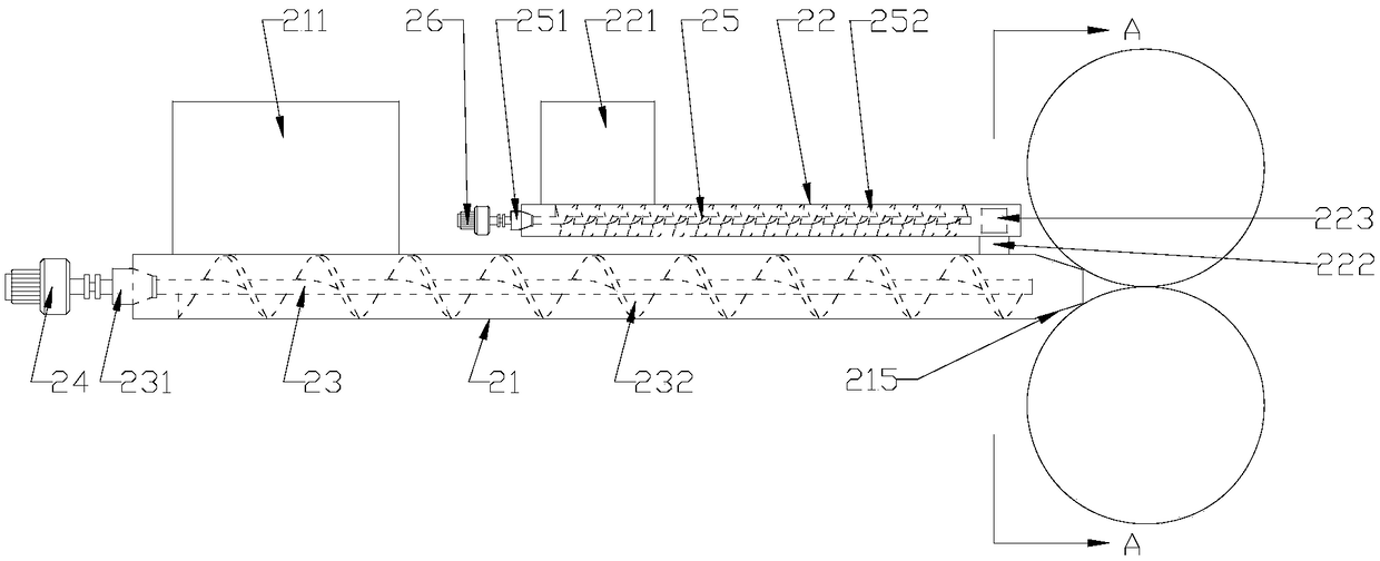
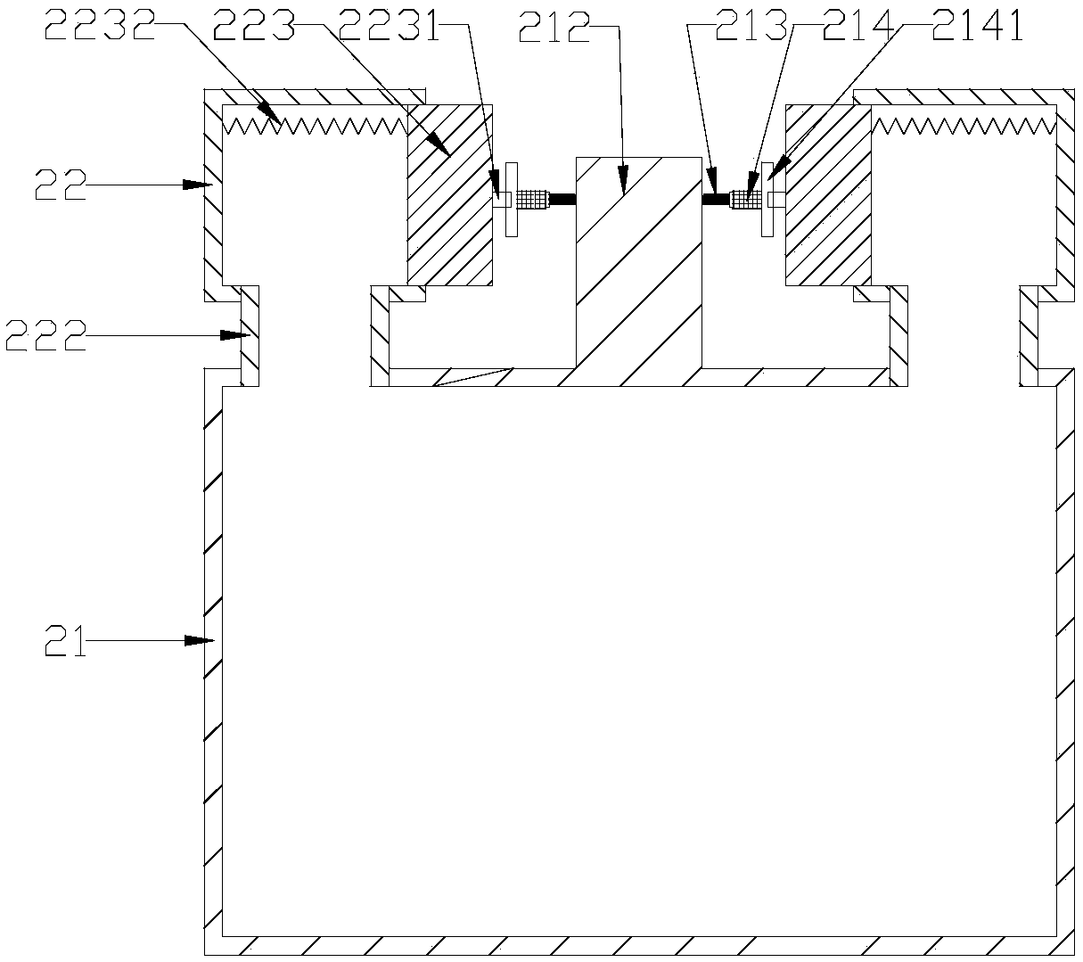
[0016] refer to figure 1 and figure 2 , a screw conveyor of the present invention includes a main conveying unit and an auxiliary conveying unit, the main conveying unit includes a first material conveying housing 21, a first rotating rod 23 and a first motor 24, and the auxiliary conveying unit includes two Set of the second material delivery housing 22, the second rotating rod 25 and the second motor 26, the auxiliary conveying unit is located on both sides of the upper end of the main conveying unit, and the first rotating rod 23 and the second rotating rod 25 respectively pass through The first bearing seat 231 and the second bearing seat 251 are fixed on the first material delivery housing 21 and the second material delivery housing 22, and the output shafts of the first motor 24 and the second motor 26 are respectively connected to the first motor 24 and the second motor 26 through a coupling. The first rotating rod 23 is connected with the second rotating rod 25, the ...


PUM


Abstract

The invention discloses a spiral conveyor, which comprises a main conveying unit and an auxiliary conveying unit, wherein the main conveying unit comprises a first material conveying shell, a first rotating rod and a first motor; the auxiliary conveying unit comprises two groups of second material conveying shells, a second rotating rod and a second motor; the auxiliary conveying unit is positioned at upper and lower sides of the main conveying unit, the first rotating rod and the second rotating rod are respectively fixed on the first material conveying shell and the second material conveyingshells through a first bearing seat and a second bearing seat, the output shafts of the first motor and second motor are respectively connected with the first rotating rod and the second rotating rodthrough couplers, the first material conveying shell is provided with a first material feeding channel, the second material conveying shells are provided with a second material feeding channel and amaterial supplementing channel, and the other end of the material supplementing channel is communicated with the first material conveying shell, so that the distribution uniformity of the material pushed out by a frustum-shaped contraction end can be kept, and the phenomenon of different thicknesses of pressed sheets can be reduced.

Description

【Technical field】 [0001] The invention relates to the technical field of feeding devices, in particular to the technical field of a screw conveyor. 【Background technique】 [0002] The rapid development of my country's PVC industry provides a good market guarantee and broad development space for the development of the heat stabilizer industry, and also puts forward higher requirements for the heat stabilizer industry. According to the development plan of my country's plastics industry, the demand for heat stabilizers will reach about 540,000 tons in 2015. [0003] The production of calcium zinc organic stabilizer does not involve chemical reaction, and the process can be divided into 4 steps: raw material weighing, mixing, granulation and packaging. The feeding mechanism is an important part of the dry granulator, usually including a hopper and a screw conveying mechanism under the hopper. The powder material enters the screw conveying mechanism through the material guide p...

Claims


Application Information

Patent Timeline
Patent Type & Authority Applications(China)
IPC IPC(8): B65G33/26B65G33/14B65G33/24
CPCB65G33/265B65G33/14B65G33/24B65G2201/04
Inventor 范豪马月秋顾炯磊
Owner 欣好科技有限公司
Why Eureka
Try Eureka