Supercharge Your Innovation With Domain-Expert AI Agents!

Photo-thermal integrated control burner

A comprehensive control and burner technology, applied in the direction of control of combustion, burner, combustion method, etc., can solve problems such as inability to stay away, environmental pollution, and inability to ensure sufficient combustion, etc., to achieve the effect of sufficient combustion

Pending Publication Date: 2019-01-18
蓬莱市海正机械配件有限公司
View PDF8 Cites 0 Cited by
  • Summary
  • Abstract
  • Description
  • Claims
  • Application Information

AI Technical Summary

Problems solved by technology

The disadvantage of this kind of burner is that the combustion state cannot be detected in time, the fuel is not fully utilized, and even the insufficiently burned smoke can be seen at the smoke exhaust port, which pollutes the environment. In order to adjust the combustion state in time, the staff cannot stay away from the noise comparison Big equipment, bad working environment
The invention patent of patent No. 2018104148186 is mainly a photoelectric control burner, which controls the combustion state by adjusting the air volume through the intensity of light, but the light intensity value is the largest, which is not the state of full combustion. The sensor senses the feedback signal changes and cannot adjust the air volume in time. The opening of the damper is controlled by the light intensity sensor, which cannot guarantee sufficient combustion. Therefore, a temperature sensor is installed to detect the flame combustion temperature and compare the temperature value set by the system. The servo motor automatically adjusts the size of the damper and the fuel supply to achieve the best combustion state.

Method used


Image

  • Photo-thermal integrated control burner
  • Photo-thermal integrated control burner
  • Photo-thermal integrated control burner

Examples


Embodiment Construction

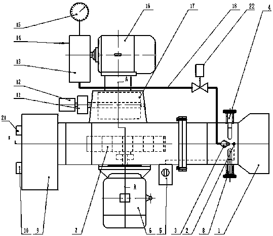
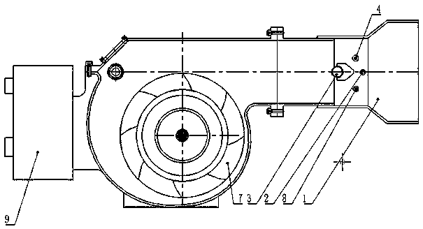
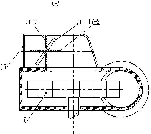
[0013] Such as figure 1 As shown, the photothermal integrated control burner of the present invention includes a fuel supply device composed of a high-pressure pump 13, an oil inlet pipeline 14, a pressure gauge 15, an oil supply motor 16, and an electric regulating valve 22; Air supply system consisting of reducer 11, damper shutter adjustment servo motor 12, impeller 7, and impeller motor 6; control device consisting of control box 9, light intensity control instrument 10, and temperature control instrument 21; light intensity sensing device 8; ignition Combustion system composed of device 5, temperature sensor 4, fuel injector 3, ignition needle 2, diffusion cover 1, etc. When the system starts, first set the highest temperature value in the temperature setting instrument 21, start the impeller motor 6, the ignition device 5 and the oil supply motor 16 in sequence, and at this time, the fuel oil is delivered to the high-pressure oil pump 13 by the oil inlet pipe 14, and the...


PUM


Abstract

The invention provides a photo-thermal integrated control burner. The photo-thermal integrated control burner comprises a fuel supply device, an air supply system, a control device, a light intensityinduction device, a temperature induction device and a combustion system, firstly, a light intensity sensor automatically inducts and adjusts the oil (gas) volume and an air door to reach a maximum light intensity value, secondly, according to a set maximum combustion temperature value of different fuels, a temperature sensor inducts a temperature value, the temperature value is compared with theset temperature value, and the air door is fine-tuned again to approach the set temperature value to achieve the integrated control of the light intensity and temperature. The light intensity sensor feeds back a control signal to the control device, an oil door is opened to the maximum supply amount position, so that the air inlet volume is matched with the oil (gas) volume to achieve the maximumlight intensity value, the temperature sensor inducts and detects the combustion temperature, the air door is fine-tuned automatically, so that the actual combustion temperature reaches the set temperature, and the fuel is burned fully.

Description

technical field [0001] The invention relates to a combustion device for industrial boilers, drying and heating equipment, in particular to a combustion device capable of controlling fuel combustion through light and thermal induction. Background technique [0002] The fuel oil and gas burners currently on the market are all fuel oil (gas) atomized and burned under a certain pressure. By observing the combustion state of the flame, mechanically or manually adjusting the damper, pressure or fuel (gas) ) volume and air volume, adjust the combustion state, and the operator will monitor it at any time. The disadvantage of this kind of burner is that the combustion state cannot be detected in time, the fuel is not fully utilized, and even the insufficiently burned smoke can be seen at the smoke exhaust port, which pollutes the environment. In order to adjust the combustion state in time, the staff cannot stay away from the noise comparison Big equipment, bad working environment. ...

Claims


Application Information

Patent Timeline
Patent Type & Authority Applications(China)
IPC IPC(8): F23D11/24F23N3/00F23N5/08
CPCF23D11/24F23N3/00F23N5/08
Inventor 王宏一孙中华
Owner 蓬莱市海正机械配件有限公司
Features
  • R&D
  • Intellectual Property
  • Life Sciences
  • Materials
  • Tech Scout
  • Unparalleled Data Quality
  • Higher Quality Content
  • 60% Fewer Hallucinations
Learn More