
High-precision measuring method for three-dimensional shape of surface of large-sized measured part

A three-dimensional shape, high-precision technology, applied in the field of visual measurement and reverse engineering, can solve the problems of low point cloud precision, difficulty in meeting large-scale zeros, high-precision three-dimensional surface of parts, high efficiency, and all-round measurement requirements

Active Publication Date: 2019-01-18
DALIAN UNIV OF TECH
View PDF5 Cites 40 Cited by
  • Summary
  • Abstract
  • Description
  • Claims
  • Application Information

AI Technical Summary

Problems solved by technology

[0003] In order to solve the problem that existing measurement equipment and data splicing methods are difficult to meet the requirements of large-scale parts and three-dimensional surfaces of components with high precision, high efficiency, and all-round measurement, because the line laser scanner can only measure X and Z axis information, it lacks Province Y axis
The invention overcomes the problem of low accuracy of point cloud acquisition by traditional measurement methods and binocular vision methods, has high measurement accuracy, high efficiency, good robustness, and has a good application prospect

Method used


Image

  • High-precision measuring method for three-dimensional shape of surface of large-sized measured part
  • High-precision measuring method for three-dimensional shape of surface of large-sized measured part
  • High-precision measuring method for three-dimensional shape of surface of large-sized measured part

Examples


Embodiment Construction

[0054] The specific embodiments of the present invention will be described in detail below in conjunction with technical methods and accompanying drawings.

[0055] The laser tracker used in the test is the AT960 model of Swiss Leica Company, and the single-point measurement accuracy is ±15μm+6μm / m. The line laser scanner is LJ-7060 produced by Keyence Corporation of Japan. The X-axis accuracy is 5 μm, the Z-axis repeat measurement accuracy is 0.4 μm, the scanning object distance and depth of field are 60±8 mm, and the line laser scanning line length is 15 mm. The PI electronic control platform is M521.DD1 produced by PI Company in Germany, with an accuracy of 0.1 μm; the specification of the matte ceramic ball is 30±0.0013mm.

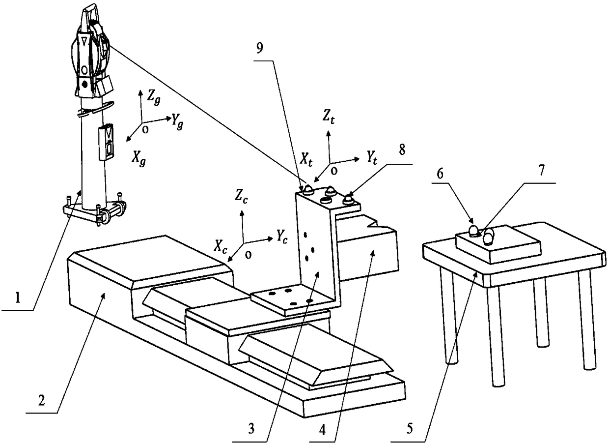
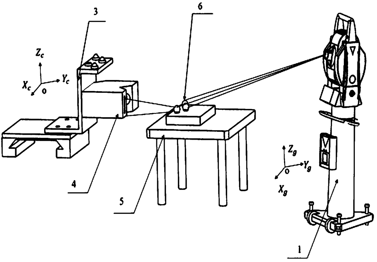
[0056] figure 1 It is a schematic diagram of the scanning measurement device for the tested part using a line laser scanner. It is composed of a line laser scanner, a PI electronic control platform, a laser tracker, a laser tracker target ball and oth...


PUM


Abstract

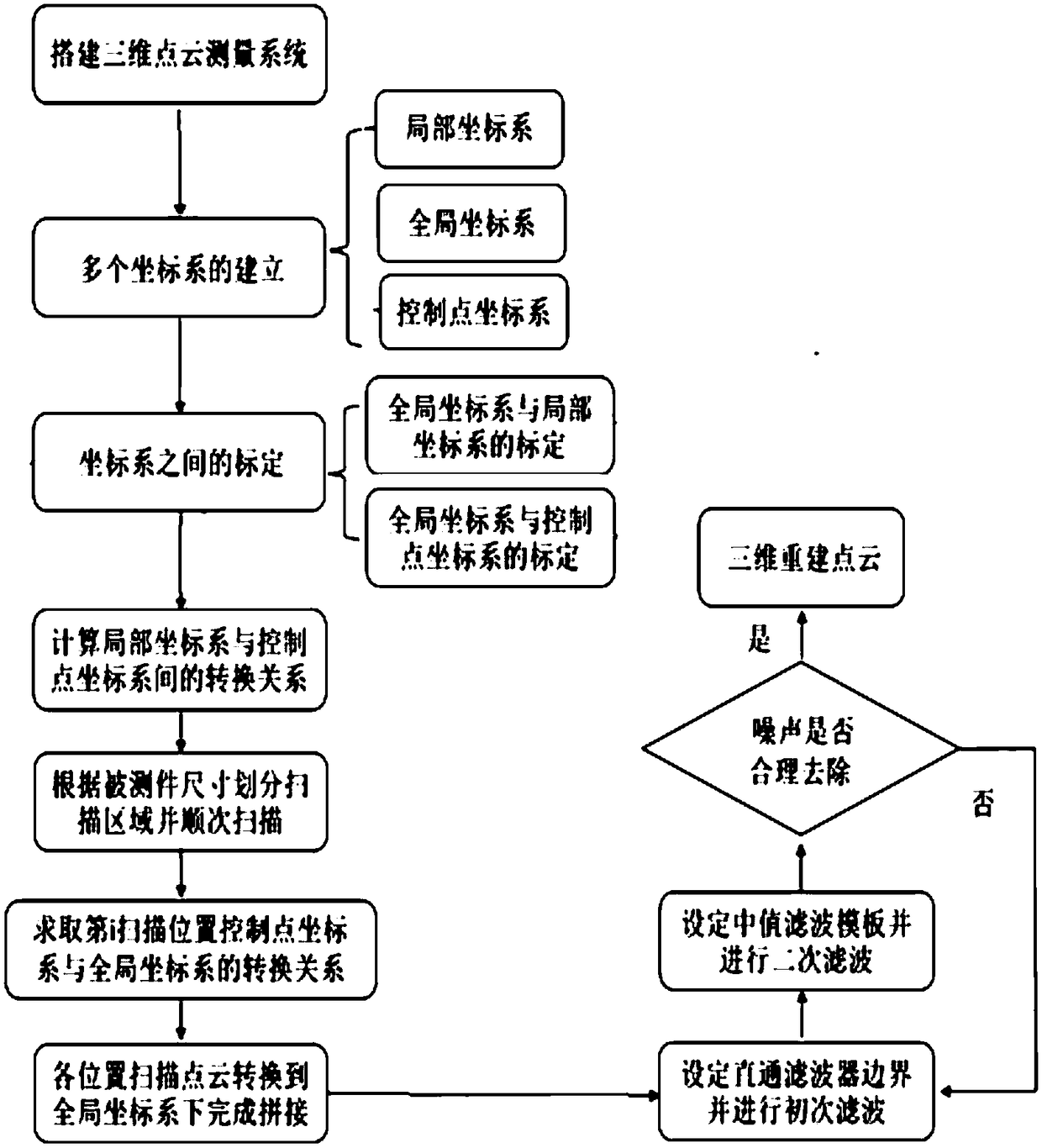
The invention discloses a high-precision measuring method for the three-dimensional shape of the surface of a large-sized measured part, belongs to the field of visual measurement and reverse engineering, and relates to a line laser scanner-based high-precision measuring method for the three-dimensional shape of the surface of the large-sized measured part. According to the method, a high-precision three-dimensional point cloud acquisition system is built by utilizing a line laser scanner and a PI electric control platform, and multi-station high-precision splicing is realized by the aid of alaser tracker. A control point coordinate system is adopted as a transition coordinate system for local and global coordinate system conversion, and the laser tracker is used for recording each position of the three-dimensional point cloud acquisition system. All data point clouds are transformed to a global coordinate system through a quaternion coordinate transformation method to complete the splicing, noises are removed by a filter, and the three-dimensional geometric shape of the surface of the measured part is reconstructed based on a least square method. According to the method, the splicing process is simplified, the splicing precision is improved, and the problem that a traditional non-contact type measuring method is unlikely to meet the high-precision, high-efficiency and high-robustness measurement requirements of the large-sized measured part at the same time is improved.

Description

technical field [0001] The invention belongs to the field of visual measurement and reverse engineering, and relates to a high-precision measurement method for the three-dimensional shape of the surface of a large-scale measurement piece using a line laser scanner. Background technique [0002] With the continuous improvement of the manufacturing process level and the continuous development of the precision manufacturing field, higher requirements are put forward for the geometric measurement accuracy of the surface of large-sized workpieces. Traditional measurement methods are difficult to meet the requirements of high precision, high efficiency, and high robustness. Require. Optical measurement equipment such as 3D laser scanners and line laser scanners are widely used in high-precision measurement sites due to their high measurement accuracy and high efficiency. In large-scale measurement sites, due to problems such as occlusion and large size of the measured part, it is...

Claims


Application Information

Patent Timeline
IPC IPC(8): G01B11/24
CPCG01B11/24
Inventor 刘巍逯永康张致远邸宏图张洋贾振元
Owner DALIAN UNIV OF TECH
Learn More