Detection device and detection method for axial force of anchor rod

A detection device and a technology of an anchor rod, applied in the field of sensors, can solve the problems of affecting the measurement accuracy, low sensitivity of the detection coil, poor air gap consistency, etc.

Inactive Publication Date: 2019-01-18
TAIYUAN UNIV OF TECH
View PDF27 Cites 2 Cited by
  • Summary
  • Abstract
  • Description
  • Claims
  • Application Information

AI Technical Summary

Problems solved by technology

[0009] (1) The large air gap leads to low sensitivity of the detection coil, so the signal-to-noise ratio is not high, making it difficult to popularize and a

Method used


Image

  • Detection device and detection method for axial force of anchor rod
  • Detection device and detection method for axial force of anchor rod
  • Detection device and detection method for axial force of anchor rod

Examples


Embodiment 1

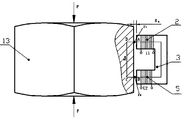
[0093] Such as figure 1 Shown is a bolt axial force detection device composed of a control circuit and a two-pole U-shaped magnetic core 3 wound with an excitation coil 2 and a detection coil 5 . When the detection device is placed on the surface of the fastening nut 13 of the tested anchor rod or at a certain air gap, and the excitation coil 2 is passed through a high-frequency alternating current, an alternating magnetic flux is generated on the excitation pole, which passes through the air. Gap and the measured bolt fastening nut 13 and the detection device constitute a closed magnetic circuit. When the bolt fastening nut 13 is subjected to the axial force F of the bolt, its magnetic permeability μ will change and the reluctance R will change, which will cause a change in the magnetic flux, and then the output voltage U2 in the detection coil 5 will change, through Measuring the magnitude of the voltage U2 can measure the magnitude of the axial force of the bolt.

[0094]...


PUM


Abstract

The invention discloses a detection device and a detection method for the axial force of an anchor rod. An integrated structure of the device is a regular hexagonal prism; an upper end cover and a lower end cover are respectively connected with a protective shell through fastening screws; a plurality of two-pole U-shaped magnetic cores are uniformly disposed at an outer side of an anchor rod fastening nut; the two-pole U-shaped magnetic cores are located in a space encircled by the upper end cover, the lower end cover and the protective shell; silicon rubber sleeves are sleeved on two magneticpoles of the two-pole U-shaped magnetic cores; a magnetic fluid is filled in each of the silicon rubber sleeves; a circuit slot is disposed in the space encircled by the upper end cover, the lower end cover and the protective shell; a control circuit is disposed in the circuit slot; a wire led from the control circuit passes through the circuit slot to wind an excitation coil and a detection coilto upper and lower ends of the two-pole U-shaped magnetic cores; elastic sheets are disposed at outer sides of the two-pole U-shaped magnetic cores; and the elastic sheets are fixed on an inner wallof the protective shell. The detection device and the detection method for the axial force of the anchor rod are used for detecting the axial force of the anchor rod, the collapse and cave-in of a topplate are avoided, a top plate support parameter is provided, and a reliable technical parameter is provided for support design of a laneway layout and safety monitoring of the top plate.

Description

technical field [0001] The invention relates to a detection device and a detection method for the axial force of a bolt, belonging to the field of sensors. Background technique [0002] Bolt support, as the main way of rock-soil anchor support technology, represents the development direction of coal mine roadway support technology. In recent years, due to the continuous extension of the excavation surface and the continuous expansion of the mining area, coal mine roof accidents have occurred from time to time, and most of the accidents are caused by poor support quality and lack of detection. Therefore, in order to ensure the safety of personnel and property, it is necessary to detect the state of the axial force of the bolt in a timely, accurate, fast and convenient manner within the service life of the roadway supported by the bolt. [0003] Chinese patent CN104913818A discloses a method of using pressure sensors, displacement sensors and monitoring instruments to monitor...

Claims


Application Information

Patent Timeline
IPC IPC(8): G01L1/12
CPCG01L1/127
Inventor 赵利平梁义维张晓俊刘润爱罗康王坤
Owner TAIYUAN UNIV OF TECH
Why Eureka
Try Eureka