Hole cutting fluid recycling device of digital controlled lathe

A technology of CNC machine tools and recycling devices, which is applied to metal processing machinery parts, maintenance and safety accessories, metal processing equipment, etc., can solve the problems of small contact area between electromagnet and cutting fluid, low removal efficiency, and inability to remove metal impurities. Achieve the effect of solving poor filtering effect, high cleaning efficiency and improving cleaning effect

Inactive Publication Date: 2019-01-22
温映格
View PDF5 Cites 16 Cited by
  • Summary
  • Abstract
  • Description
  • Claims
  • Application Information

AI Technical Summary

Problems solved by technology

[0005] In this way, the contact area between the electromagnet and the cutting fluid is small, and the

Method used


Image

  • Hole cutting fluid recycling device of digital controlled lathe
  • Hole cutting fluid recycling device of digital controlled lathe
  • Hole cutting fluid recycling device of digital controlled lathe

Examples


Embodiment 1

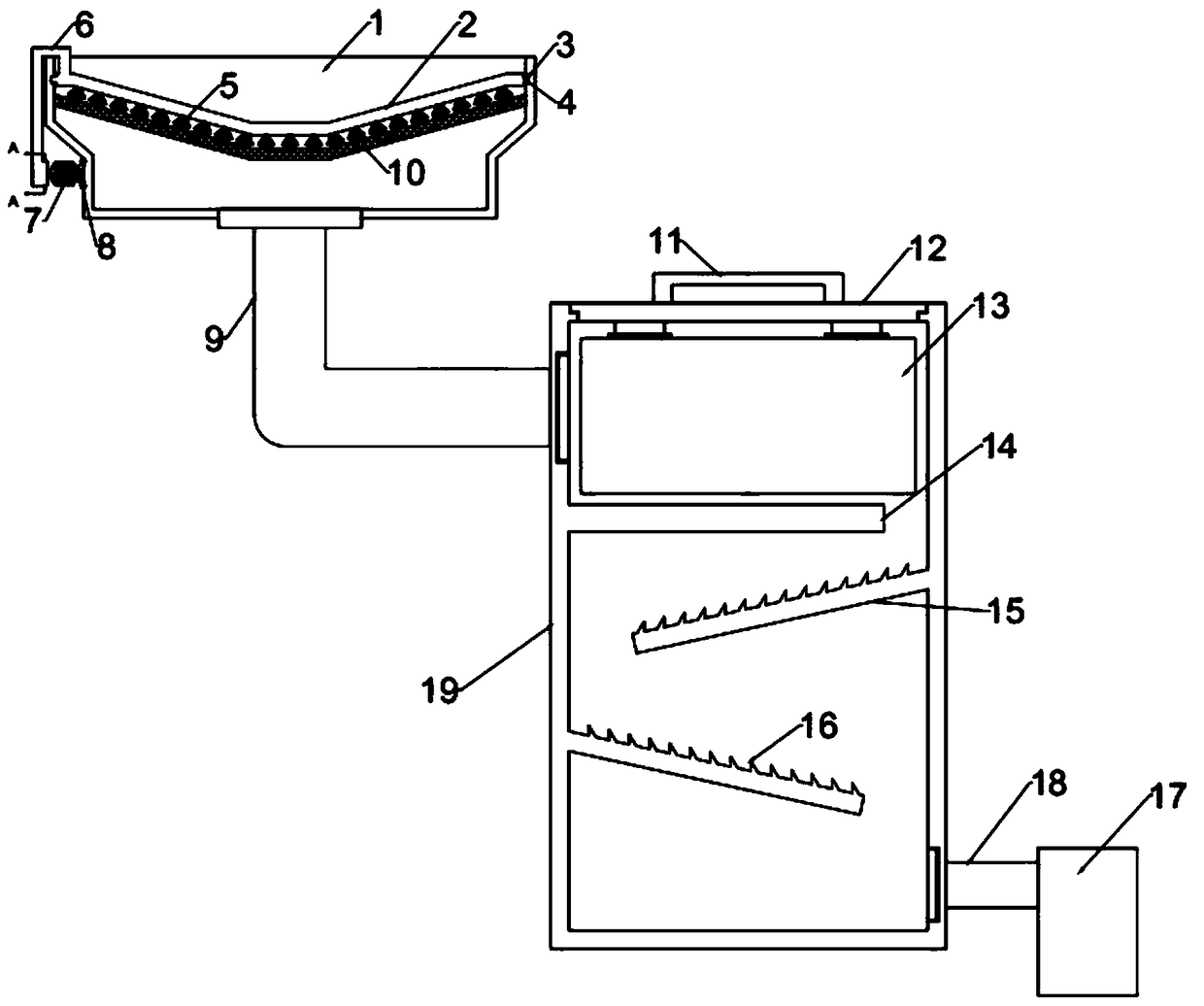
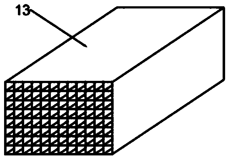
[0022] see Figure 1~3 , in an embodiment of the present invention, a CNC machine tool hole cutting fluid recovery device includes a receiving tray 1, a collection bucket 17 and a purification bucket 19; one side of the purification bucket 19 communicates with the receiving tray 1 through a connecting pipe 9, and the purification bucket The other side of 19 is communicated with collection bucket 17 by conduit 18, and filter screen 10 is installed in the described receiving dish 1, carries out primary filtration by filter screen 10 and then enters purification treatment in purification bucket 19, and described purification bucket 19 is provided with A partition 14, the upper end of the partition 14 is provided with a grid-shaped electromagnet 13, the two ends of the grid-shaped electromagnet 13 are connected and aligned with the water outlet of the connecting pipe 9, and the cutting fluid in the connecting pipe 9 enters In the grid-shaped electromagnet 13, the grid-shaped elect...

Embodiment 2

[0025] Since a large amount of metal impurities will be produced when the product is processed by a numerical control machine tool, if a large amount of metal impurities are accumulated on the filter screen 10, the filtering effect of the filter screen 10 will be affected. Therefore, this embodiment is optimized. Specifically, on the filter screen 10 A scrubbing mechanism is provided, and the scrubbing mechanism includes a brush plate 2, a slide bar 6 and a motor 7, and the two ends of the brush plate 2 are fixed with a slider 3, and the slider 3 is slidably installed in the chute 4 arranged on the inner wall of the receiving tray 1, Thus, the sliding connection between the brush plate 2 and the receiving tray 1 is realized.

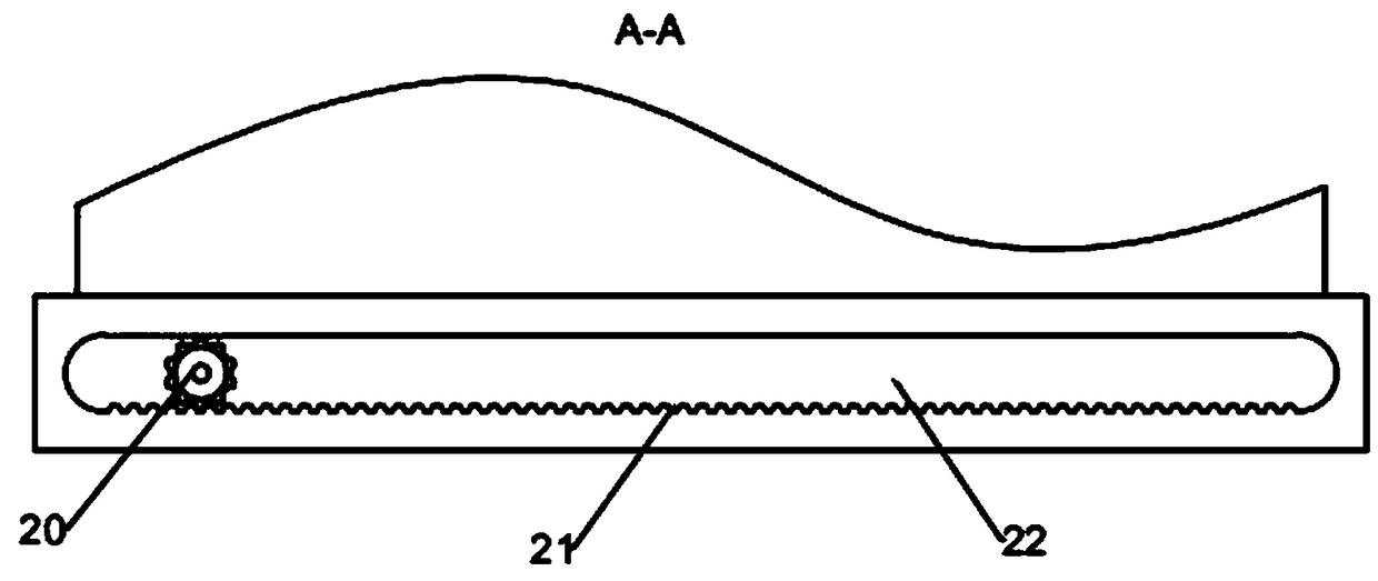
[0026] Described brush plate 2 is fixedly connected with the bar plate that is provided with bar groove 22 through slide bar 6, and bar groove 22 is provided with bar tooth 21, and bar tooth 21 is fixed on the output shaft of motor 7 The gear 20 meshes, ...


PUM


Abstract

The invention discloses a hole cutting fluid recycling device of a digital controlled lathe. The hole cutting fluid recycling device of the digital controlled lathe comprises a receiving plate, a collecting barrel and a purifying barrel; one side of the purifying barrel communicates with the receiving plate through a communicating tube; the other side of the purifying barrel communicates with thecollecting barrel through a guide tube; a filter screen is mounted in the receiving plate; a partition is arranged in the purifying barrel; a grating-shaped electromagnet is arranged at the upper endof the partition; the two ends of the grating-shaped electromagnet are conductive; and an inclined electromagnet is arranged in the cavity of the lower end of the partition. The hole cutting fluid recycling device of the digital controlled lathe is novel in design, by arrangement of the grating-shaped electromagnet, metal impurities in cutting fluid are sucked and removed, and the grating-shaped electromagnet can be fully in contact with the cutting fluid, the metal impurities in the cutting fluid are increased, the removing effect is good, by arrangement of the inclined electromagnet, the flowing time of the cutting fluid in the purifying barrel can be prolonged, therefore, the impurity removal effect is improved, a strip-shaped projection is fixed on the inclined electromagnet, and the metal impurity removing effect can further be improved.

Description

technical field [0001] The invention relates to the technical field of numerical control machine tools, in particular to a device for recovering cutting fluid from holes in numerical control machine tools. Background technique [0002] CNC lathe is one of the most widely used CNC machine tools at present. It is mainly used for cutting the inner and outer cylindrical surfaces of shaft parts or disk parts, the inner and outer conical surfaces of arbitrary cone angles, the complex rotary inner and outer curved surfaces, cylinders, and conical threads, etc., and can perform grooving, drilling, reaming, and reaming. Holes and borings etc. [0003] Cutting fluid is an industrial liquid used in metal cutting and grinding to cool and lubricate cutting tools and workpieces. Cooling performance, lubricating performance, anti-rust performance, degreasing and cleaning function, anti-corrosion function, easy to dilute. It overcomes the shortcomings of traditional soap-based emulsions,...

Claims


Application Information

Patent Timeline
IPC IPC(8): B23Q11/10
CPCB23Q11/10B23Q11/1069
Inventor 温映格
Owner 温映格
Why Eureka
Try Eureka