A multifunctional ball end milling cutter

A ball-end milling cutter, multi-functional technology, applied in the direction of milling cutters, milling cutting blades, milling machine equipment, etc., can solve the problems that affect the overall performance of ball-end milling cutters, poor processing surface quality, cutting edge wear, etc., to improve processing Good surface quality, good surface quality and light cutting effect

Active Publication Date: 2020-06-02
ZHUZHOU CEMENTED CARBIDE CUTTING TOOLS CO LTD
View PDF15 Cites 0 Cited by
  • Summary
  • Abstract
  • Description
  • Claims
  • Application Information

AI Technical Summary

Problems solved by technology

Although the structure of the ball end milling cutter is simple, but limited by the process, the single ball cutting edge has constant structural parameters such as rake angle and relief angle.
Since the main cutting part of the ball end milling cutter is the ball end cutting edge part, the ball cutting edge starts from the central axis with zero diameter and ends at the largest diameter column cutting edge, the cutting speed of the ball cutting edge is quite different, especially in the center The cutting line speed is basically zero, and the cutting edge in the central area wears rapidly and is prone to chipping during cutting. The strength of the central cutting edge can be improved by optimizing the parameters such as rake angle and relief angle, but it will lead to a sharp increase in cutting force, Problems such as large vibration and poor surface quality seriously affect the overall performance of the ball end milling cutter, and the failure of the central cutting edge has become the main failure mode of the ball end milling cutter
Therefore, the diameter of the cutting spherical surface around the center of the ball cutting edge of the ordinary ball end milling cutter is equal to the cutting edge diameter of the ball end milling cutter. In order to reduce the surface residue and ensure the surface quality, only low cutting feed can be used for each machining. low efficiency

Method used


Image

  • A multifunctional ball end milling cutter
  • A multifunctional ball end milling cutter
  • A multifunctional ball end milling cutter

Examples


Embodiment 1

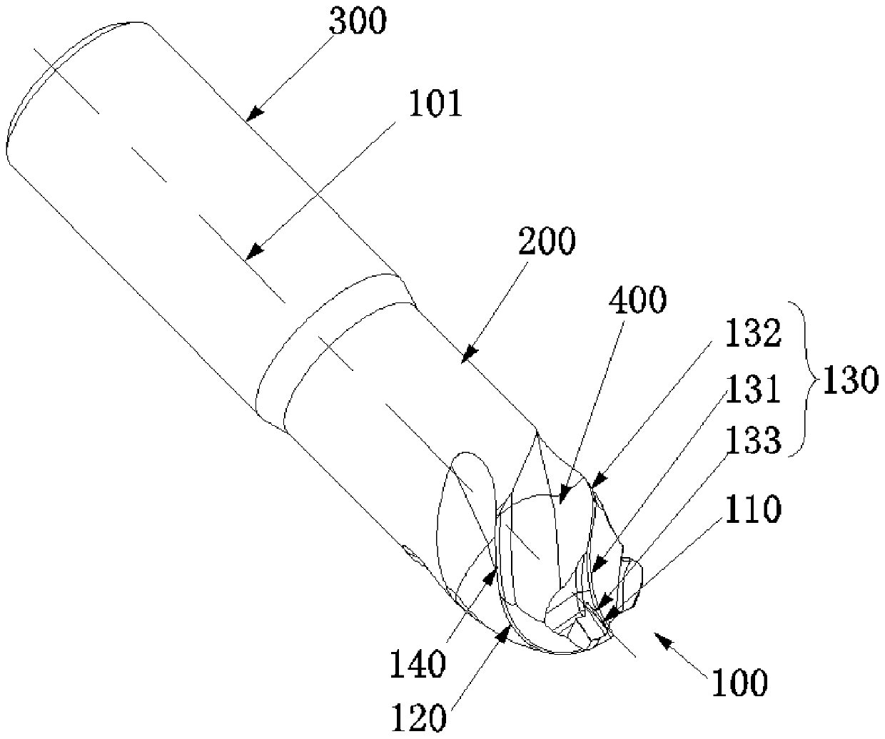
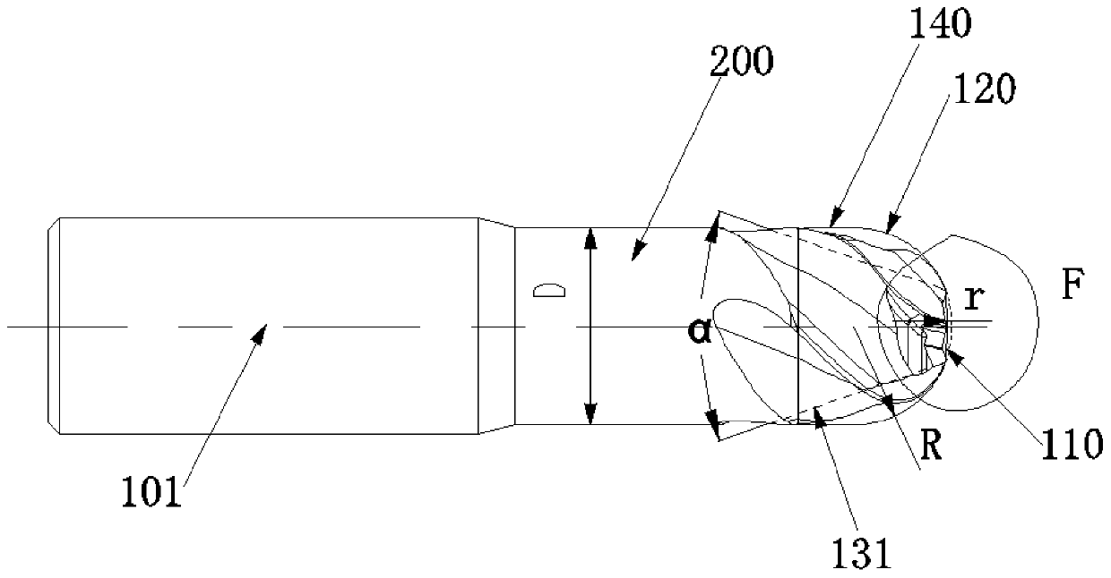
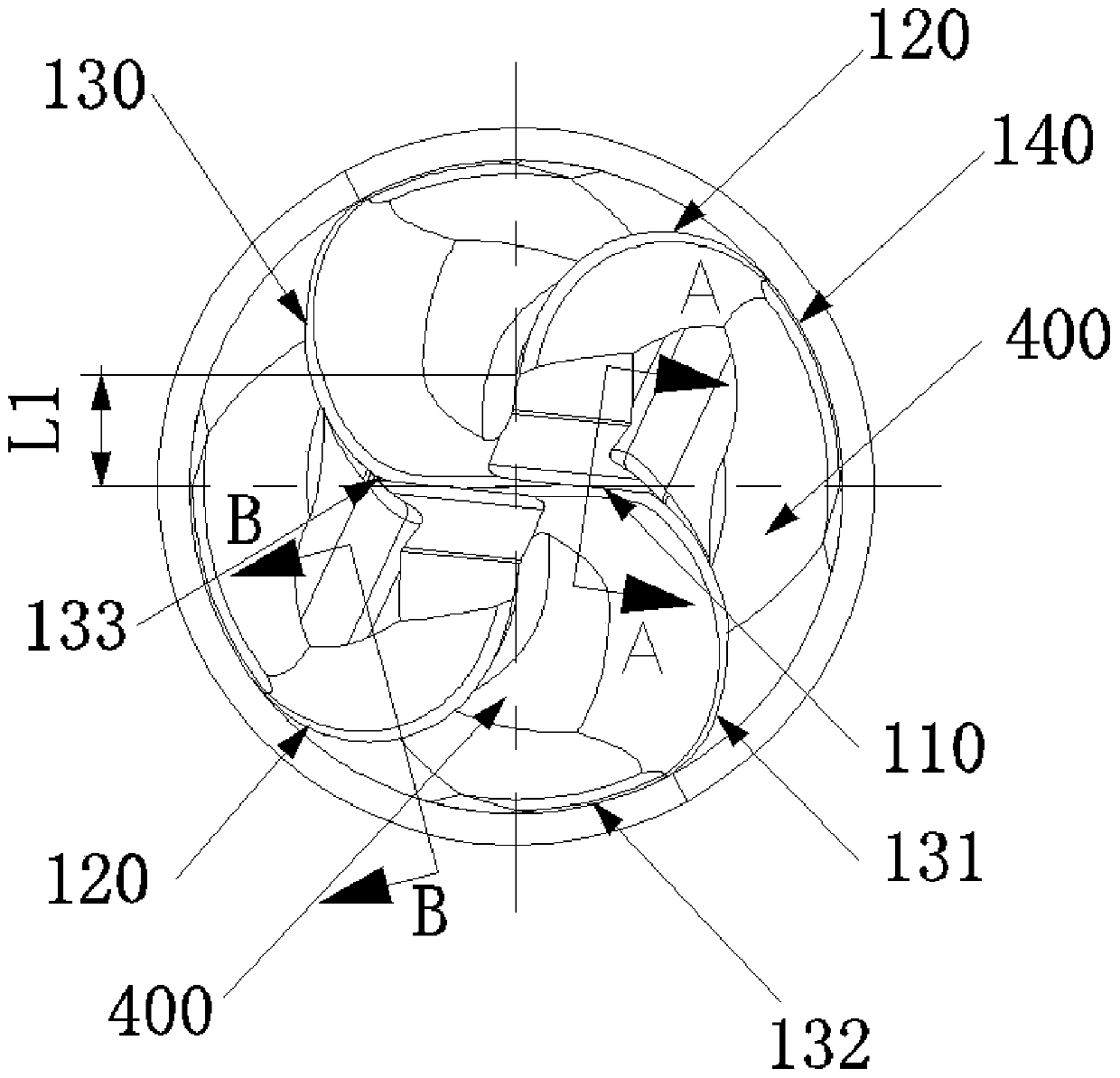
[0041] like Figure 1 to Figure 6 As shown, the multifunctional ball end milling cutter of the present embodiment includes a cutting part 100, a loading and unloading part 300, and a connecting part 200 for connecting the cutting part 100 and the loading and unloading part 300. The cutting part 100 has a central axis 101, and the cutting part 100 includes An inner spherical cutting edge 110 and at least one pair of outer spherical cutting edges 120, the inner spherical cutting edge 110 intersects with the central axis 101 and is rotationally symmetrical about the central axis 101, two outer spherical cutting edges 120 in each outer spherical cutting edge 120 are about the center The axis 101 is rotationally symmetrical, and there is a certain radial distance between the outer spherical cutting edge 120 and the central axis 101, the spherical surface formed by the inner spherical cutting edge 110 rotating about the central axis 101 and the spherical surface formed by the outer s...

Embodiment 2

[0052] like Figure 7 to Figure 9 As shown, the multifunctional milling cutter of the present embodiment is basically the same as Embodiment 1, and the difference is only in:

[0053] In this embodiment, the connecting edge 130 has the same structure as the outer spherical cutting edge 120 , and both are rotationally symmetrical about the central axis 101 . That is to say, the connecting edge 130 is milled in the same way as the outer spherical cutting edge 120 . The chip flutes 400 are formed by the area between the connecting edge 130 and the outer spherical cutting edge 120 , and the connecting edge 130 has the same structure as the outer spherical cutting edge 120 , so the four chip flutes 400 have the same structure. That is, in this embodiment, the cutting edge is divided into one inner spherical cutting edge 110 and four outer spherical cutting edges 120 . There is a transitional cutting edge 150 with a smooth transition between the connecting edge 130 and the inner s...

Embodiment 3

[0056] like Figure 10 and Figure 11 As shown, in the multifunctional ball end milling cutter of this embodiment, the cutting part 100 includes an inner ball cutting edge 110 and an outer ball cutting edge 120, the inner ball cutting edge 110 intersects the central axis 101, and the intersection point cuts the inner ball The cutting edge 110 is divided into two sections, the length of one section is longer than the length of the other section. There is a certain radial distance between the outer spherical cutting edge 120 and the central axis 101; The spherical surface formed by the rotation of the spherical cutting edge 120 about the central axis 101 intersects. The spherical surface radius of the inner spherical cutting edge 110 is r, and the spherical surface radius of the outer spherical cutting edge 120 is R, satisfying: 5R≤r≤15R.

[0057] In this embodiment, only one end of the inner ball cutting edge 110 has a connecting edge 130 between the connecting portion 200, an...


PUM


Abstract

The invention discloses a multifunctional ball endmill which includes a cutting portion, an assembly and disassembly portion and a connecting portion for the cutting portion, the assembly and disassembly portion. The cutting portion includes an inner ball cutting edge and at least one pair of outer ball cutting edges. The inner ball cutting edge and a central shaft are cross and are rotatably symmetric with respect to the central shaft, two outer ball cutting edges in each pair of outer ball cutting edges are rotatably symmetric with respect to the central shaft, a radial spacing is reserved between the outer ball cutting edges and the central shaft, a spherical surface formed by the inner ball cutting edge rotating with respect to the central shaft and a spherical surface formed by the outer ball cutting edge rotating with respect to the central shaft are cross, the spherical surface radius of the inner ball cutting edge is r, and the spherical surface radius of the outer ball cuttingedge is R, meeting: 5R<=r<=15R. The spherical surface radius of the inner ball cutting edge is far greater than that of the outer ball cutting edge, and when performing cavity large feeding cutting or flat surface copy milling, the endmill has a low radial load and high cutting efficiency.

Description

technical field [0001] The invention relates to a metal cutting tool, in particular to a multifunctional ball end milling cutter. Background technique [0002] Generally, the solid carbide ball end milling cutter is mainly used for profiling, cavity and ball groove processing. The cutting part of ordinary ball end milling cutter is mainly composed of ball cutting edge or ball cutting edge and column cutting edge. Integrity of profiling processing ability, when at least one spherical cutting edge rotates around the central axis for cutting, the cutting spherical surface is not less than half a spherical surface. In order to make the feed of each cutting edge of the ball end milling cutter uniform and the cutting stable, the single ball cutting edge of the ball end milling cutter adopts a continuous cutting edge structure, and all the ball cutting edges on the ball end milling cutter are distributed on the central axis. on the same sphere with constant diameter and perfect co...

Claims


Application Information

Patent Timeline
Patent Type & Authority Patents(China)
IPC IPC(8): B23C5/10
CPCB23C5/1018B23C2200/088
Inventor 江爱胜吴火飞李屏汤爱民倪兰薛俊波
Owner ZHUZHOU CEMENTED CARBIDE CUTTING TOOLS CO LTD
Why Eureka
Try Eureka