Aluminum alloy split V-shaped thrust rod and preparation method and hot riveting assembly method thereof
A technology of aluminum alloy and thrust rod, which is applied in metal processing equipment, forging/pressing/hammer devices, forging presses, etc., can solve the problems of heavy thrust rod weight and poor lightweight effect, and achieve high degree of automation and high yield , high performance effect
- Summary
- Abstract
- Description
- Claims
- Application Information
AI Technical Summary
Problems solved by technology
Method used
Image

Examples
Embodiment 1
[0125] The composition of thrust rod among the embodiment one is:
[0126] the element
Amount (mass percentage, wt%)
Si
1.2
Mg
1.2
Fe
0.6
Cu
5.5
mn
0.5
Cr
0.08
Ni
0.05
Zn
0.20
Ti
0.15
Zr
0.05
Sr
0.03
Er
0.005
Ce
0.01
Al
balance, and unavoidable impurities.
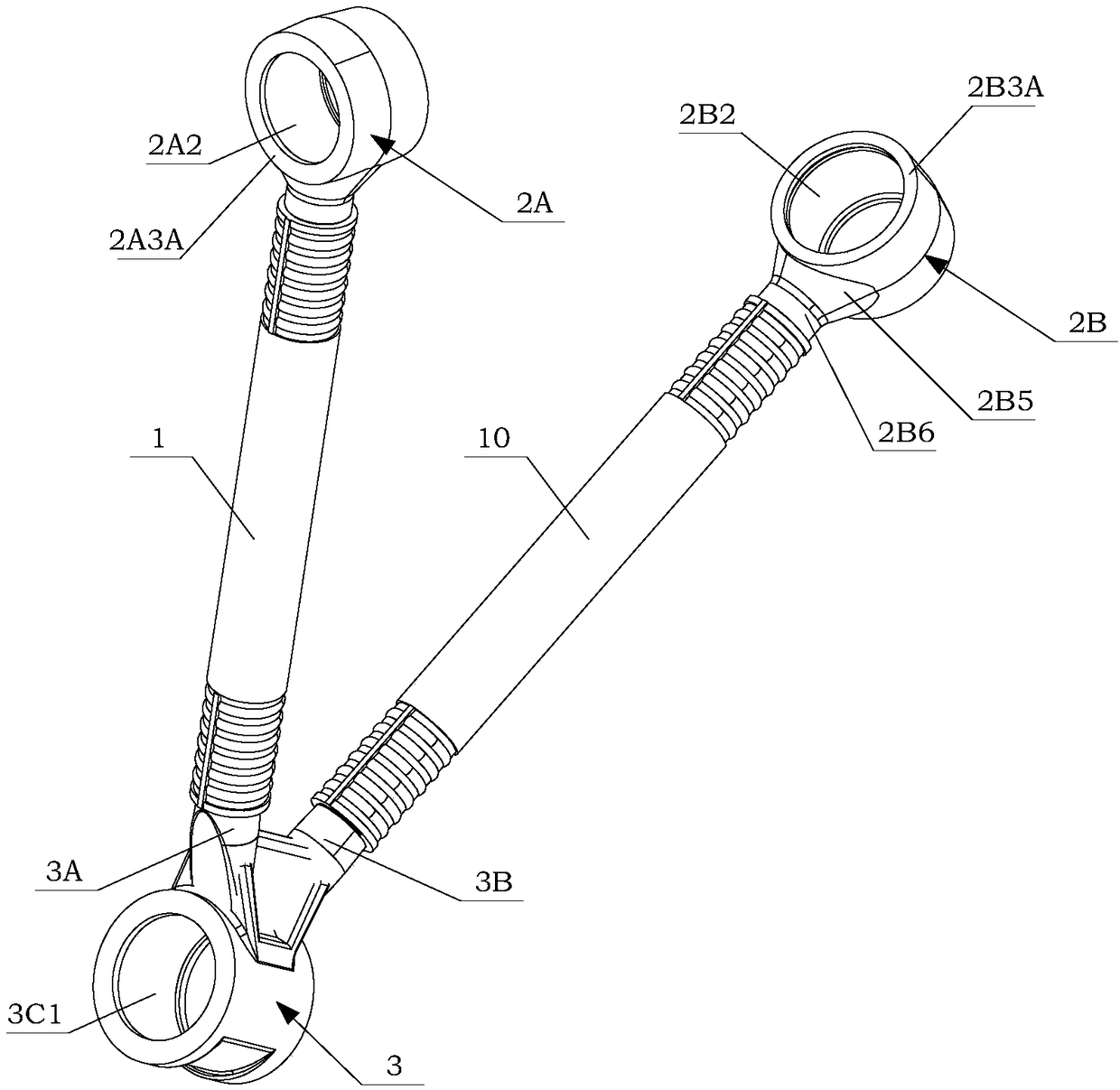
[0127] Overall length L of casing 1 1 =810mm, inner radius r of casing 1 1A =30mm; the maximum outer radius r of the bellows section of A ball head 2A 2A1 = 30mm, the maximum outer radius of the bellows section of the V-shaped ball head 3 is 30mm; the radius of the neck arc section (2A6, 2B6) of the A ball head is The major radius of the elliptical segments (2A5, 2B5) is Oa=135mm, and the minor radius is Ob=90mm.
[0128] The sleeve preparation process is hot extrusion molding, and the process is as follows:
[0129] Step 101, preparing an aluminum ...
PUM
| Property | Measurement | Unit |
|---|---|---|
| Average tensile strength | aaaaa | aaaaa |
| Yield strength | aaaaa | aaaaa |
Abstract
Description
Claims
Application Information