
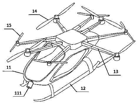
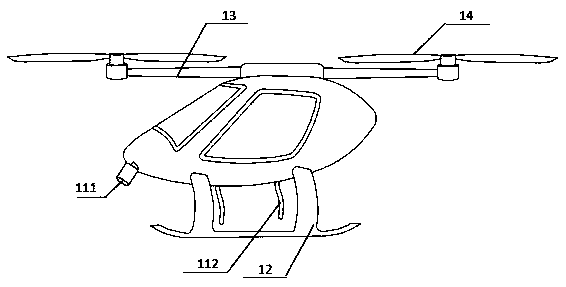
Eight-rotor manned vehicle

An aircraft and eight-rotor technology, applied in the field of aircraft, can solve the problems of short battery life, poor load capacity, stability, and flexibility, and achieve the effect of prolonging flight time, improving flight power, and improving flexibility.

Inactive Publication Date: 2019-01-25
FOSHAN SHENFENG AVIATION SCI & TECH
View PDF0 Cites 2 Cited by
  • Summary
  • Abstract
  • Description
  • Claims
  • Application Information

AI Technical Summary

Problems solved by technology

[0003] However, due to the limitation of the above-mentioned aircraft rotor, its stability and flexibility are not high. If the rotor is added, the energy consumption will be increased. Since the aircraft is generally small in size and has little available space, it only relies on electric power to provide power, so the battery life is short. , the load capacity is poor, and it cannot meet the needs of current aircraft in disaster rescue, surveying and mapping, inspection, logistics and transportation. If oil power is used to provide power, the rotor needs to control the direction while providing lift, making it stable and flexible. Greatly reduced

Method used


Image

  • Eight-rotor manned vehicle
  • Eight-rotor manned vehicle
  • Eight-rotor manned vehicle

Examples


Embodiment 1

[0051] The pilot enters the manned cabin to drive and presses the start button to turn on the aircraft. At this time, the hybrid electric system provides flight power for the aircraft. The diesel engine drives the large rotor to provide lift for the aircraft, and the motor drives the small rotor to provide lift. When the two rotors rotate at the same time and the speed is the same, the reaction torque generated by each group of rotors to the fuselage is the same in value, and the directions are opposite, so they can cancel each other, so that the aircraft is balanced in the horizontal direction and remains stable. When you need to adjust the aircraft to rise to a high place to observe the overall environment, control the left-hand control lever to increase the rotation speed of the large rotor, so that the total lift provided by the rotation of the rotor increases, and the aircraft rises; when you need to adjust the aircraft to descend and land closer to the ground So that when ...

Embodiment 2

[0053] When the pilot needs to adjust the route while driving the aircraft, he can adjust the attitude adjustment by controlling the right-hand joystick to adjust the speed of the small rotor. The small rotor 1 and the small rotor 4 are located in the front half of the aircraft. Through algorithm calculation and microcomputer control, the final setting is that when the right-hand control lever swings to the left and front, the rotation speeds of small rotor 1 and small rotor 3 decrease at the same time, and the rotation speeds of small rotor 2 and small rotor 4 increase at the same time, because small rotor 1 and small rotor 3 Rotate clockwise, small rotor 2 and small rotor 4 rotate counterclockwise. At this time, the anti-torque generated by the counterclockwise rotor group on the fuselage is greater than the anti-torque generated by the clockwise rotor on the fuselage, so the aircraft will deflect in the counterclockwise direction , That is, adjust the route to the left; simi...

Embodiment 3

[0055] When the pilot needs to make a pitching motion to avoid obstacles in front of the aircraft while driving the aircraft, he controls the right-hand joystick to change the speed of the small rotor to adjust the attitude. When the right-hand control lever swings forward, the speeds of small rotor 1 and small rotor 4 increase at the same time, and the speeds of small rotor 2 and small rotor 3 decrease at the same time. At this time, the lift of the front part of the aircraft increases, and the lift of the second half of the aircraft decreases. Flight motion; in the same way, reduce the speed of small rotor 1 and small rotor 4, increase the speed of small rotor 2 and small rotor 3, and do a bird's-eye flight motion. Due to the pitch motion, the aircraft and the horizontal plane form a pitch angle, so the lift provided by the rotor produces a horizontal component that makes the aircraft move forward and backward, causing the aircraft to move forward and backward at the same time...


PUM


Abstract

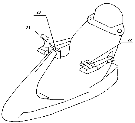
The invention discloses an eight-rotor manned aircraft comprising the aircraft body and flight control system, a main body of that aircraft include a manned cabin, a landing gear, a support arm fixedly connected to the manned cabin and a rotor fixed to the support arm, the manned cabin comprises a seat, a left control lever and a right control lever for controlling flight, and a display system forobserving the position information of the aircraft, and the environment state of the aircraft during flight can be observed through image information captured by a rocking camera installed at the front end of the aircraft; the manned cabin comprises a left control lever and a right control lever for controlling flight. The flight control system is divided into two parts to control the setting ofthe rotor, so that the aircraft has more power and more flexibility; Hybrid power supply ensures the power source. Hybrid power supply converts the excess energy of light load into electric energy when the aircraft is decelerated or descended, thus achieving the purpose of saving fuel and fast starting, and prolonging the sailing time.

Description

Technical field [0001] The invention relates to the technical field of aircraft, and more specifically to an eight-rotor manned aircraft. Background technique [0002] At present, with the development of materials, electronics and computer control technology, multi-rotor UAVs have been widely used in aerial photography, surveillance and other fields. Multi-rotor aircraft can take off and land vertically, hover for a long time, and have strong maneuverability. At the same time, it has the advantage of being smaller than helicopters. Therefore, it has convenient transportation under special conditions such as high-rise buildings, facilities, cliffs, rivers, and mountains. Rotorcraft includes three-axis single (double) rotors, four-axis single (double) rotors, and six-axis rotors. [0003] However, due to the limitations of the above-mentioned aircraft rotors, its stability and flexibility are not high. If the rotors are added, the energy consumption will be increased. Because the a...

Claims


Application Information

Patent Timeline
Patent Type & Authority Applications(China)
IPC IPC(8): B64C27/08B64D9/00B64D27/02B64D31/00
CPCB64C27/08B64D9/00B64D27/02B64D31/00B64D27/026
Inventor 王鹏飞王志成
Owner FOSHAN SHENFENG AVIATION SCI & TECH
Learn More