
Deep hole self-centering in-tube robot

A self-centering, robotic technology, applied in the direction of instruments, measuring devices, etc., can solve the problems of inability to accurately measure the straightness of deep hole parts, affecting the accuracy of straightness measurement, and inability to achieve on-machine measurement. Accuracy and stability, reducing measurement costs, increasing the effect of motion stability

Active Publication Date: 2019-01-25
DALIAN UNIV OF TECH
View PDF11 Cites 10 Cited by
  • Summary
  • Abstract
  • Description
  • Claims
  • Application Information

AI Technical Summary

Problems solved by technology

[0003] Research on deep hole straightness detection at home and abroad continues to deepen, but compared with other measurement items, deep hole straightness detection technology is lagging behind. In actual production applications, workers often use the plug gauge method to evaluate whether parts are Qualified, but cannot accurately measure the straightness of deep hole parts
There are also deep hole inspections based on single laser PSD. The reflector is perpendicular to the axis of the deep hole parts to be measured through the centering mechanism, and the reflector is pulled by a rope to move in the deep hole, and the PSD sensor is used for measurement, but the device needs to be installed. Precise adjustment and fixing, otherwise it will greatly affect the accuracy of straightness measurement, which is affected by site restrictions and operator proficiency, and on-machine measurement cannot be realized, and the parts need to be removed for measurement after each processing procedure , affecting the accuracy of subsequent processing
[0004] However, the price of some high-precision straightness testing instruments is relatively expensive, which is unacceptable.

Method used


Image

  • Deep hole self-centering in-tube robot
  • Deep hole self-centering in-tube robot
  • Deep hole self-centering in-tube robot

Examples


Embodiment Construction

[0040] In order to make the purpose, technical solutions and advantages of the embodiments of the present invention clearer, the technical solutions in the embodiments of the present invention will be clearly and completely described below in conjunction with the drawings in the embodiments of the present invention. Obviously, the described embodiments It is a part of embodiments of the present invention, but not all embodiments. Based on the embodiments of the present invention, all other embodiments obtained by persons of ordinary skill in the art without making creative efforts belong to the protection scope of the present invention.

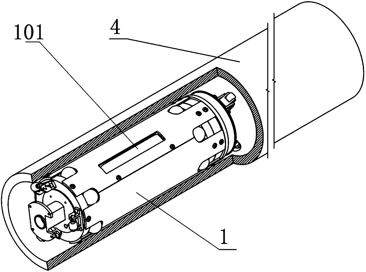
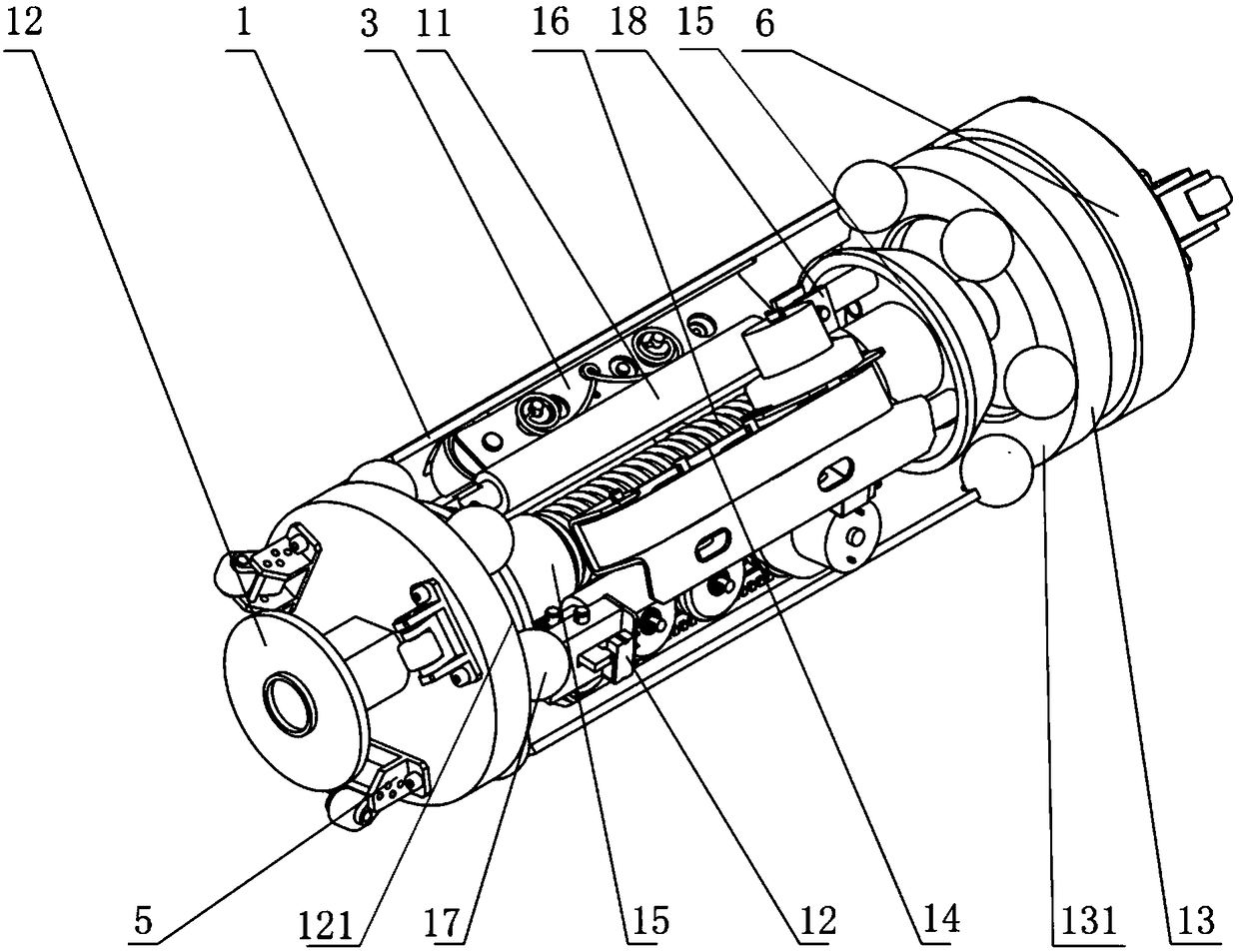
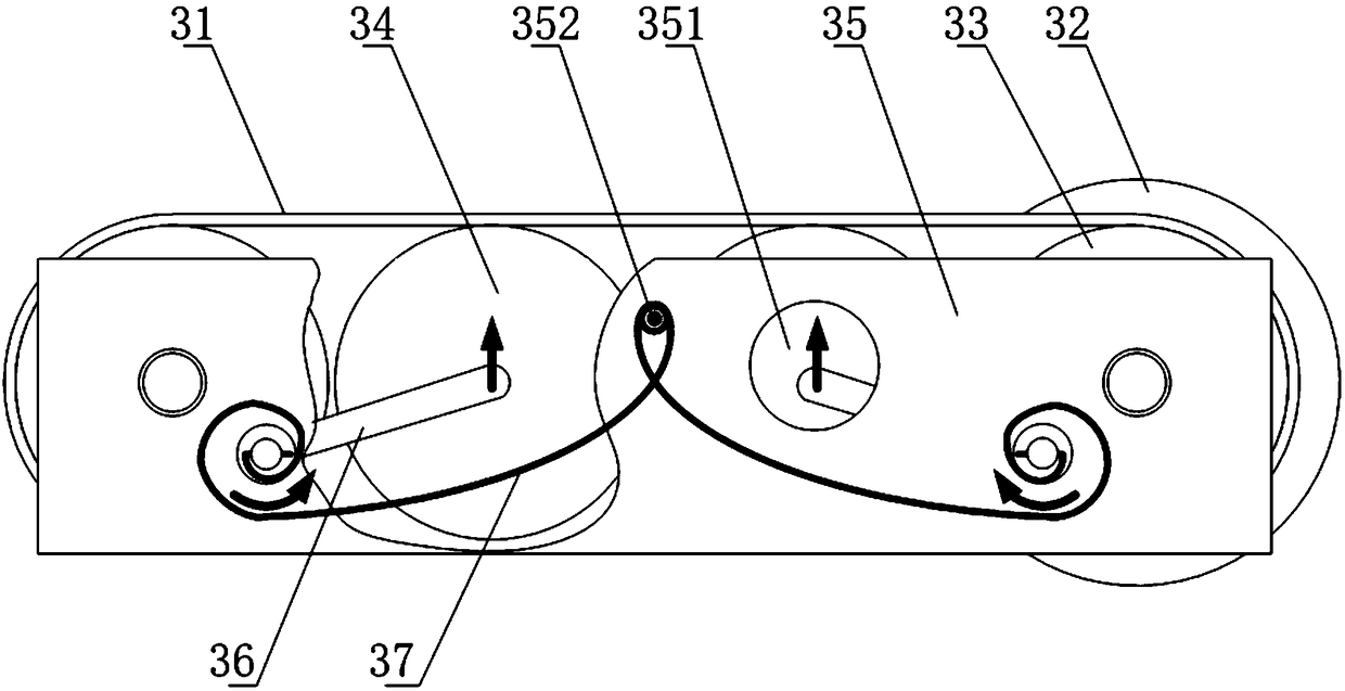
[0041] Such as Figure 1-Figure 8 As shown, a deep-hole self-centering in-pipe robot includes a protective shell 1, three electric push rods 11 arranged in the protective shell 1, and the two ends of the protective shell 1 are respectively fixed with reflector bases. Seat 12, tail base 13, one end of the reflector base has a flat end face I1...


PUM


Abstract

The invention discloses a deep hole self-centering in-tube robot. The robot comprises a protective cylindrical shell and a plurality of electric push rods disposed in the protective cylindrical shell;a reflector base and a tail base are respectively fixed to two ends of the protective cylindrical shell; a mandrel is directly fixed to the reflector base and the tail base; the mandrel is sleeved with two taper shafts that are in transitional fit with the mandrel; a plurality of centering ceramic balls are clamped between the reflector base and the thin end of the taper shaft, as well as betweenthe tail base and the thin end of the taper shaft which is adjacent to a flat end surface II; and a track running mechanism is disposed between every two adjacent electric push rods. According to thedeep hole self-centering in-tube robot of the invention, the balls are adopted to realize centering, so that line-contact centering can be converted into point-contact centering; the accuracy of thecentering is greatly increased due to an error equalization effect; the push rods and force bearing rings are combined, so that stability in the centering process can be improved; and the track type running mechanisms are adopted and are distributed circumferentially and evenly, and therefore, the stability of motion can be greatly increased.

Description

technical field [0001] The invention relates to the technical field of geometric accuracy detection of parts with a large depth-to-diameter ratio, in particular to a deep hole self-centering in-pipe robot. Background technique [0002] At present, the cannon barrel is one of the most critical parts of the cannon. Its function is to give the projectile a certain initial velocity and shooting direction when the cannon is fired. The barrel directly bears the high pressure of gunpowder gas, high-temperature gas ablation and violent friction of projectiles at the moment of artillery firing, and the working conditions are extremely harsh. Its straightness directly affects the combat performance indicators such as shooting accuracy, muzzle velocity, and service life of the artillery. During the processing of the gun barrel, its quality will be greatly affected by various factors such as tool rod deformation, system chatter, workpiece material, drill parameters, cutting parameters,...

Claims


Application Information

Patent Timeline
Patent Type & Authority Applications(China)
IPC IPC(8): G01B21/00G01B21/10
CPCG01B21/00G01B21/10
Inventor 康仁科朱祥龙董志刚李崎岩戴恒震张桥杰
Owner DALIAN UNIV OF TECH
Learn More