Speckle elimination light path and three-color laser projection system

A speckle and optical path technology, applied in optics, optical components, instruments, etc., can solve the problems of high cost of dynamic speckle components, affecting the quality of projection images, and inability to meet display requirements, so as to increase the range of spatial positions and reduce chromatic aberration. , the effect of reducing the number of

Active Publication Date: 2019-01-25
SICHUAN CHANGHONG ELECTRIC CO LTD
View PDF8 Cites 5 Cited by
  • Summary
  • Abstract
  • Description
  • Claims
  • Application Information

AI Technical Summary

Problems solved by technology

Among them, the high coherence of the laser causes the speckle effect in the laser projection display. Speckle refers to that when a coherent light source illuminates a rough object, the scattered light is generated in space due to the constant phase difference, the same light wave frequency, and the same vibration direction. Interference, some parts interfere constructively, and some parts interfere destructively. The final result is that there are bright and dark spots on the screen, that is, speckle. Cause discomfort, more seriously affect the quality of the projection screen, and re

Method used


Image

  • Speckle elimination light path and three-color laser projection system
  • Speckle elimination light path and three-color laser projection system
  • Speckle elimination light path and three-color laser projection system

Examples


Embodiment 1

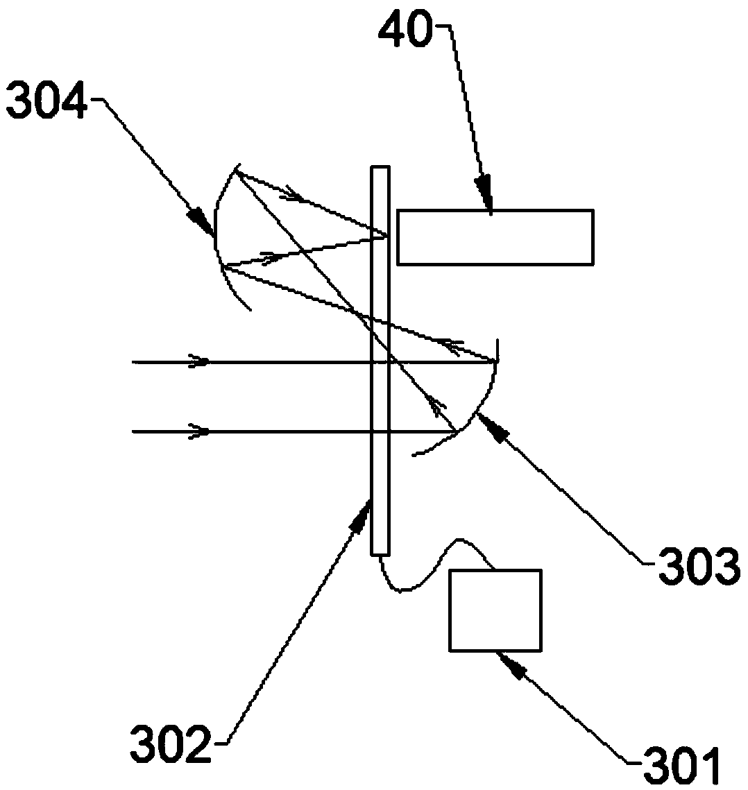
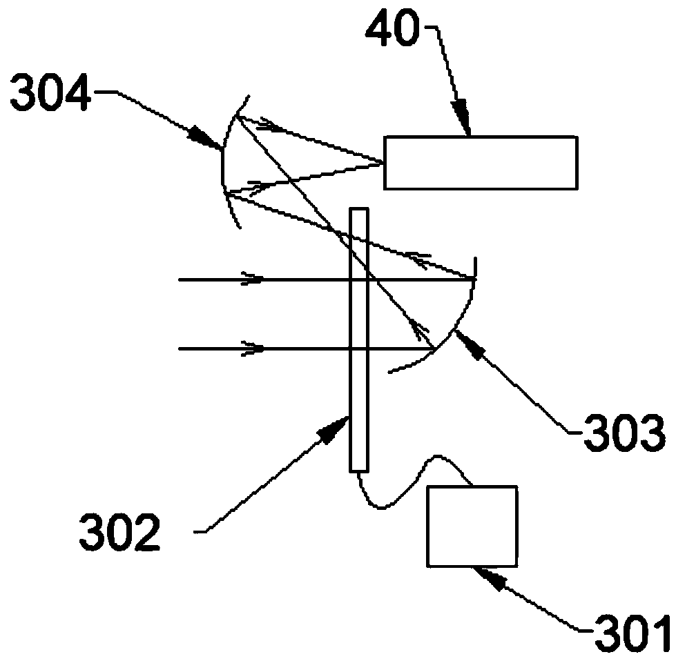
[0088] Such as figure 1 As shown, this embodiment provides a speckle-eliminating optical path including: a reflective optical path component and a dynamic de-speckle device. The dynamic de-speckle device includes a vibration controller 301 and a diffuser 302. The reflective optical path component includes a first mirror 303 and a second mirror. The reflecting mirror 304 and the light rod 40; the diffusion component 302 is placed between the first reflecting mirror 303 and the second reflecting mirror 304; the vibration controller 301 drives the diffusion component 302 to vibrate.

[0089] Preferably, in this embodiment, the first mirror 303 and the second mirror 304 are preferably curved mirrors, which can be set as spherical, hyperboloid, parabolic, ellipsoidal, or free-form surface according to technical solutions.

[0090] Such as Image 6 As shown, in this embodiment, the diffuser 302 is a square diffuser, which can be a single sheet or a combination of multiple sheets; the diff...

Embodiment 2

[0099] Such as Figure 8 As shown, in this embodiment, a speckle-eliminating optical path is provided, including: a diffuser 302, a motor 307, a first mirror 303, a second mirror 304, and a light rod 40;

[0100] Such as Picture 10 As shown, the diffuser 302 is a disc diffuser with a single-sided or double-sided frosted surface.

[0101] The optical path structure and optical principle of this embodiment are basically the same as those of the second embodiment. The difference lies in the technical solution adopted by the dynamic speckle reduction device in this embodiment: the motor 307 is coaxially connected with the diffuser 302, and the motor 307 is placed on the diffuser. On the right side of 302, the first mirror 303 and the second mirror 304 are respectively arranged on the same side of the rotating shaft of the motor 307. The motor 307 drives the diffusion member 302 to rotate around the axis at a high speed, achieving a better effect of eliminating speckle.

[0102] Such as...

Embodiment 3

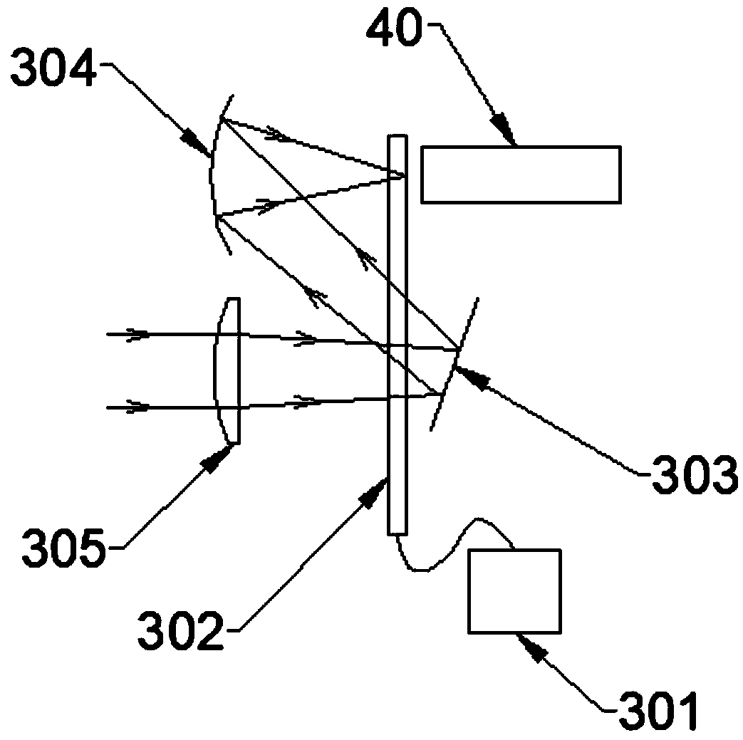
[0104] Such as Picture 11 As shown, in this embodiment, a laser defocusing optical path 30 is provided, including: a first condenser lens 305, a vibration controller 301, a diffusion component 302, an ellipsoidal mirror 308, and an optical rod 40.

[0105] Specifically, the diffusion member 302 is placed parallel to the aperture end surface of the ellipsoidal mirror 308, and the diffusion member 302 is within ±5 mm of the first focal point 309 and the second focal point 310 of the ellipsoidal surface.

[0106] The working process of the laser speckle light path 30 in this embodiment is as follows: the laser beam is incident on the first condenser lens 305, and then the laser beam is focused on the first focal point 309 of the ellipsoidal mirror 308, and the ellipsoidal mirror 308 reflects and focuses the laser beam on On the second focal point 310, a light rod 40 is placed in front of the focus point, and the laser beam is incident on the light rod 40 for uniform light.

[0107] Pre...


PUM


Abstract

The invention discloses a speckle elimination light path and a three-color laser projection system, which relate to the technical field of laser display. The three-color laser projection system comprises a reflective optical path assembly, a dynamic speckle elimination device and an optical rod, wherein the dynamic speckle elimination device comprises a diffusing component and a driving componentconnected with the diffusing component; and the reflective optical path assembly focuses a laser beam passing through the diffusing component to an inlet of the optical rod after at least one reflection. The light path turns for multiple times by means of the reflective optical path assembly, the functions of a plurality of dynamic speckle elimination devices are realized by means of only one dynamic speckle elimination device disclosed by the invention, and a good speckle elimination effect is achieved. The laser speckle elimination light path provided by the invention is simple in structure,the reflection or refraction and reflection combined light path design makes the structure of an optical machine more compact, and the miniaturization of the three-color laser projection system is easy to realize.

Description

Technical field [0001] The present invention relates to the field of laser display technology, in particular to a speckle-eliminating optical path and a three-color laser projection system. Background technique [0002] As a newly developed projection technology, laser projection uses a diode laser as a light source. The light is homogenized by the illumination system and then projected on the light modulation chip (DMD, LCD, LCOS, etc.), and then imaged on the image surface by the projection lens. Among them, the high coherence of the laser causes the speckle effect in the laser projection display. Speckle refers to that when a coherent light source illuminates a rough object, the scattered light is generated in space due to the constant phase difference, the same light wave frequency, and the same vibration direction. Interference, some parts of the interference are constructive, and some of the interferences are canceled. The final result is that bright and dark spots appear o...

Claims


Application Information

Patent Timeline
IPC IPC(8): G02B27/48G03B21/20
CPCG02B27/48G03B21/206G03B21/2066G03B21/208
Inventor 何龙姜银磊梁其鹏
Owner SICHUAN CHANGHONG ELECTRIC CO LTD
Why Eureka
Try Eureka