A staggered grid slow wave structure with sinusoidal function profile

A slow-wave structure and sine function technology, applied in the field of slow-wave structures, can solve the problems of low average coupling impedance and weak injection-wave interaction of slow-wave structures, so as to improve electron interaction efficiency and output power, increase electric field strength, Improve the effect of weak injection wave interaction

Inactive Publication Date: 2019-01-25
SHENZHEN UNIV
View PDF1 Cites 6 Cited by
  • Summary
  • Abstract
  • Description
  • Claims
  • Application Information

AI Technical Summary

Problems solved by technology

This staggered grating slow-wave structure has the following two disadvantages: (1) the electric field distribution of the slow-wave structure is strong in the middle along the broadside direction of the strip-shaped electron injection channel 11, and the distribution is

Method used


Image

  • A staggered grid slow wave structure with sinusoidal function profile
  • A staggered grid slow wave structure with sinusoidal function profile
  • A staggered grid slow wave structure with sinusoidal function profile

Examples


Embodiment Construction

[0030] In this embodiment, the sinusoidal function profile interlaced grating slow wave structure working in the G frequency band is taken as an example.

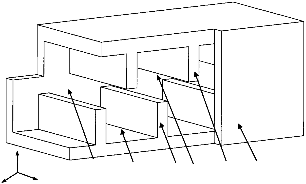
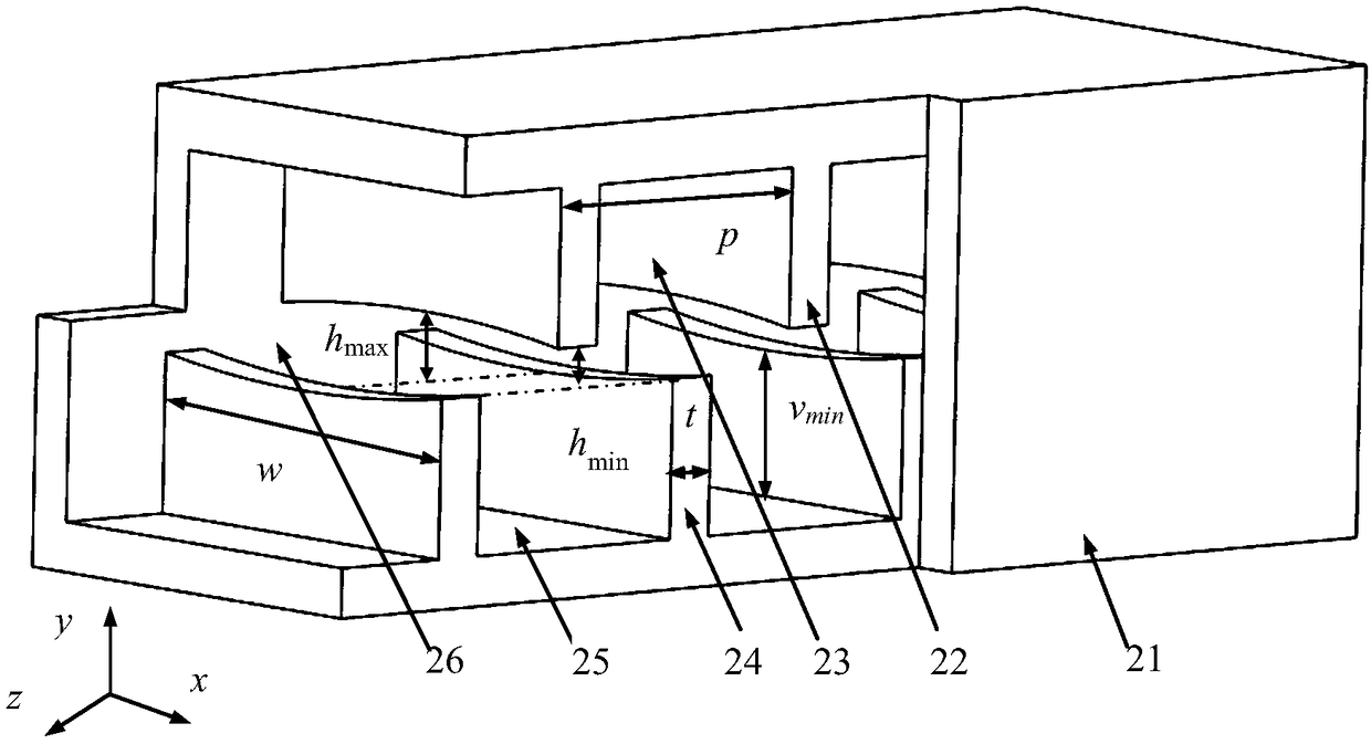
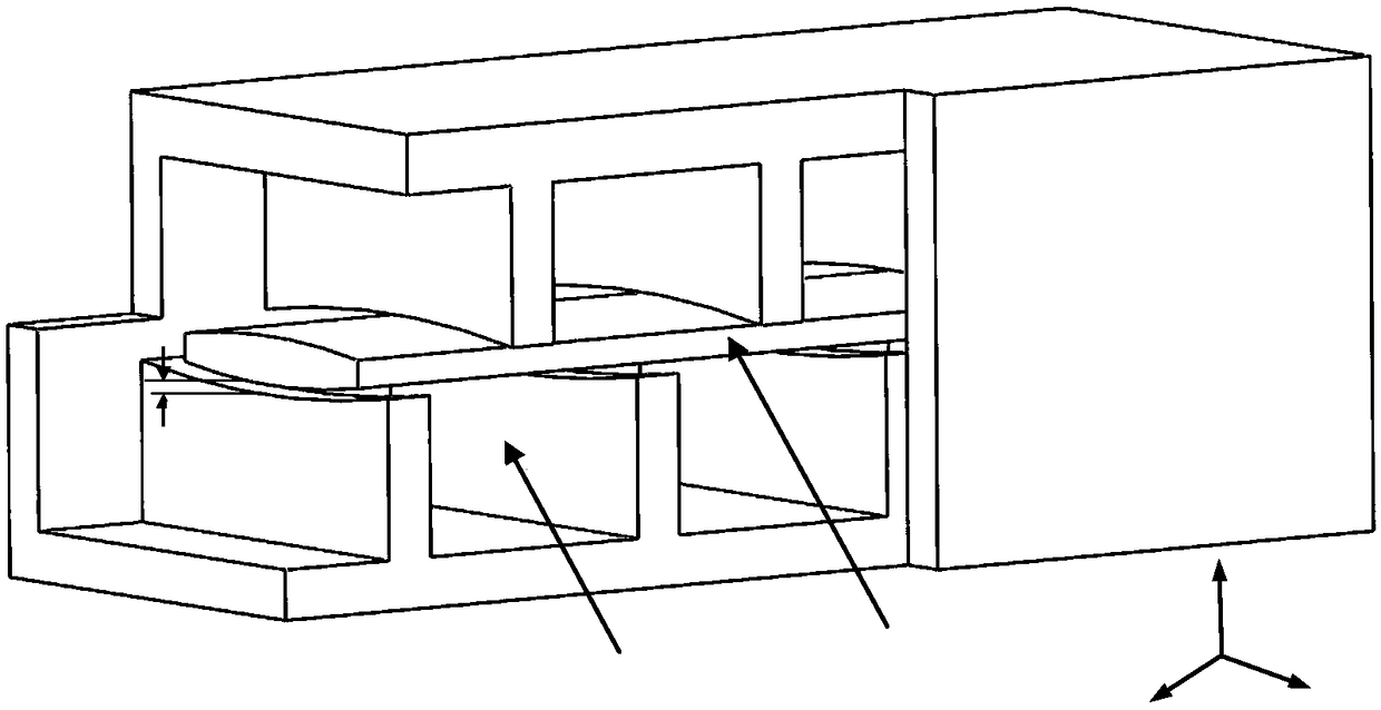
[0031] like figure 2 As shown, the staggered grid slow wave structure with sinusoidal function profile of the present invention includes a cuboid housing 21 , upper grid teeth 22 , lower cavity 23 , lower grid teeth 24 , lower cavity 25 and belt-shaped electron injection channel 26 . The structural parameters of the slow wave structure are: p=0.6mm, v min =0.29mm, w=0.84mm, t=0.1mm, h max = 0.14 mm and h min = 0.08 mm. The contours of the upper grid teeth 22 and the lower grid teeth 24 in the widthwise direction are all subject to a sine function distribution. Taking the midpoint of the left narrow side of the electron injection channel as the origin, the function corresponding to the upper grid tooth 22 is y=0.04+0.03*sin(2π / 1.68*x) (0≤x≤0.84), and the function corresponding to the lower grid tooth 24 The function is...


PUM


Abstract

The invention discloses a staggered grid slow wave structure with sinusoidal function profile, which is composed of a rectangular shell, upper/lower grid teeth, upper/lower cavities and strip injection channels. The wide-edge profile of the band-shaped electron beam channel has changed from the traditional straight-line profile to the sinusoidal profile. The distribution of the longitudinal electric field along the broad side of the slow wave structure is in good agreement with the shape of the strip channel, and the distribution is sinusoidal function. The slow-wave structure can not only increase the operating frequency but also the coupling impedance, which can compensate for the non-uniformity of the coupling impedance in the wide-side direction, thus increasing the intensity of the beam-wave interaction, and further improving the electronic efficiency and output power of the traveling wave tube/backward wave tube based on the slow-wave structure. When applied to band-beam TWT, thegain of the whole TWT can also be increased. Millimeter-wave terahertz traveling-wave tubes/backward-wave tubes based on this slow-wave structure have been widely used in many military and civil applications such as communications radar electronic countermeasures imaging and so on.

Description

[technical field] [0001] The invention belongs to the field of microwave electric vacuum technology, and in particular relates to a slow wave structure used for strip-shaped injection traveling wave tubes / return wave tubes. [Background technique] [0002] Microwave / millimeter wave / terahertz technology has a wide range of applications in many military and civilian applications such as communications, radar, electronic countermeasures, security imaging, material detection, and biomedicine. Microwave / millimeter wave / terahertz source is the basis of microwave / millimeter wave / terahertz technology and an integral part of the whole system. Microwave electric vacuum devices are very important microwave / millimeter wave / terahertz sources due to their high electron efficiency and large output power. The ribbon injection device increases the current of the electron beam by enlarging the area of ​​the electron beam, thereby increasing the output power of the whole tube. It is a micr...

Claims


Application Information

Patent Timeline
IPC IPC(8): H01J23/24
CPCH01J23/24
Inventor 舒国响钱正芳熊浩王建勋刘国何文龙张良孙一翎
Owner SHENZHEN UNIV
Why Eureka
Try Eureka