Breast tumor detection system
A detection system and breast tumor technology, applied in the medical field, can solve the problems of difficult resonance frequency and unsatisfactory recognition effect, and achieve the effect of improving tumor speed and accuracy and reducing the risk of tumor judgment
- Summary
- Abstract
- Description
- Claims
- Application Information
AI Technical Summary
Problems solved by technology
Method used
Image
Examples
Embodiment 1
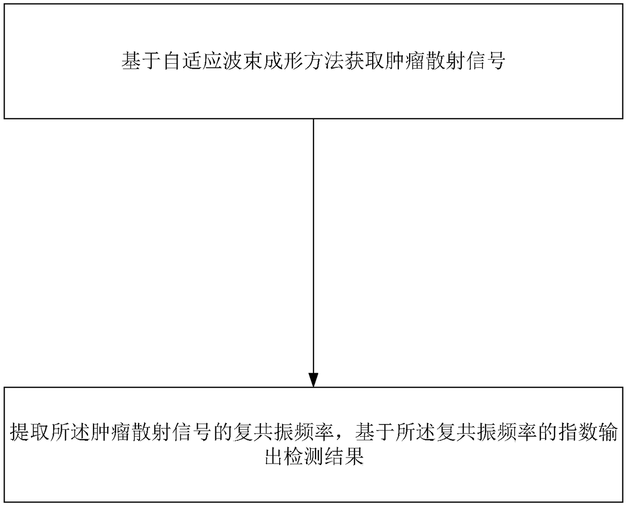
[0019] This embodiment is used to illustrate the principle and steps of the present invention to solve technical problems. During the moving process of the breast scanning spiral moving device, the main control module controls a certain port of the vector network analyzer to transmit microwave signals, and the microwave signals are transmitted to the Microwave antenna (including transmitting antenna, receiving antenna) and radiates into the space of the detection container through the microwave antenna. The microwave signal passes through or touches the breast or the test body (breast phantom) and is reflected to other microwave antennas. Other microwave antennas The received echo scattering signal is transmitted to the other signal ports of the vector network analyzer through the cable signal line, and the vector network analyzer records the echo original electromagnetic wave signal to complete a single scan. The main control module controls the sending and receiving of differe...
Embodiment 2
[0022] This embodiment is used to explain preferred scheme:
[0023] First of all, the original electromagnetic wave signal received by the microwave antenna needs to be preprocessed, including filtering and calibration, and the preprocessed signal is defined as
[0024] the y i (t)=a(t)s i (t)+e i (t)(1), where y i (t)=[y i,1 (t),...,y i,M (t)] T is the preprocessed signal vector obtained from 1 to M receiving antennas excited by the i-th transmitting antenna, s i (t) is the scattering signal excited by the i-th transmitting antenna and at any scattering point in the breast imaging space, a(t) is the steering vector of the signal, e i (t) is the sum of all interference signals and noises outside the scattering point.
[0025] In microwave imaging, the y i (t) All signals in the vector are scaled to position r in the time domain 0 , so that the steering vector reaches and make the steering vector satisfy the condition: Among them, δ is the limit value describing ...
Embodiment 3
[0031] Although the adaptive beamforming method guarantees the minimum mean square error of the signal, it cannot guarantee the most approximate estimation of the signal waveform. Therefore, this embodiment provides a minimum variance objective function on the basis of Embodiment 2, which can analyze the waveform Estimate to overcome the error in the waveform of the signal to be recovered:
[0032] First, define a new minimum mean square error objective function:
[0033]
[0034] in is the real waveform to be restored, s(t) is the real waveform and its mean value is zero, and the minimization solution of formula (8) can be obtained: W=|s| 2 (R Y +|s| 2 aa H ) -1 a(9), in order to simplify this embodiment, the time function t is omitted, then the formula (9) can also be expressed as the adaptive beamforming RCB method multiplied by the coefficient β:
[0035] W β =βW RCB (10), where, s is the unknown real signal waveform, in order to get |s| 2 For an approximate...
PUM
 Abstract
Description
Claims
Application Information
 - R&D
- Intellectual Property
- Life Sciences
- Materials
- Tech Scout
- Unparalleled Data Quality
- Higher Quality Content
- 60% Fewer Hallucinations
Browse by: Latest US Patents, China's latest patents, Technical Efficacy Thesaurus, Application Domain, Technology Topic, Popular Technical Reports.
© 2025 PatSnap. All rights reserved.Legal|Privacy policy|Modern Slavery Act Transparency Statement|Sitemap|About US| Contact US: help@patsnap.com


