An automatic pre-calibration method for concrete placing machine based on laser ranging

A technology of laser ranging and calibration method, which is applied to measuring devices, ceramic molding machines, and optical devices, etc., can solve problems such as affecting the development and implementation of automatic cloth control functions, unable to automatically determine the position of the cloth machine, and unstable product quality. , to achieve the effect of improving accuracy and pre-calibration efficiency, small changes, and low cost of transformation

Active Publication Date: 2020-07-28
SHENYANG JIANZHU UNIVERSITY
View PDF9 Cites 0 Cited by
  • Summary
  • Abstract
  • Description
  • Claims
  • Application Information

AI Technical Summary

Problems solved by technology

[0003] Due to the lack of the key technology of pre-calibration for concrete placing machines in the industry, the control system of the placing machine cannot automatically determine the position of the placing machine relative to the magnetic side form, which also affects the development and implementation of the subsequent automatic placing control function, resulting in the current concrete placing. The machine can only produce fabrics in manual operation mode, and at the same time, it needs to be equipped with a number of production assistants to assist in the uniform distribution with shovels, which not only causes problems such as low production efficiency and unstable product quality, but also poses safety hazards

Method used


Image

  • An automatic pre-calibration method for concrete placing machine based on laser ranging
  • An automatic pre-calibration method for concrete placing machine based on laser ranging
  • An automatic pre-calibration method for concrete placing machine based on laser ranging

Examples


Embodiment Construction

[0024] In order to make the purpose, technical solution and advantages of the present invention clearer, the present invention will be further described in detail below in conjunction with the accompanying drawings and specific embodiments. The specific embodiments described here are only used to explain the present invention, not to limit the present invention.

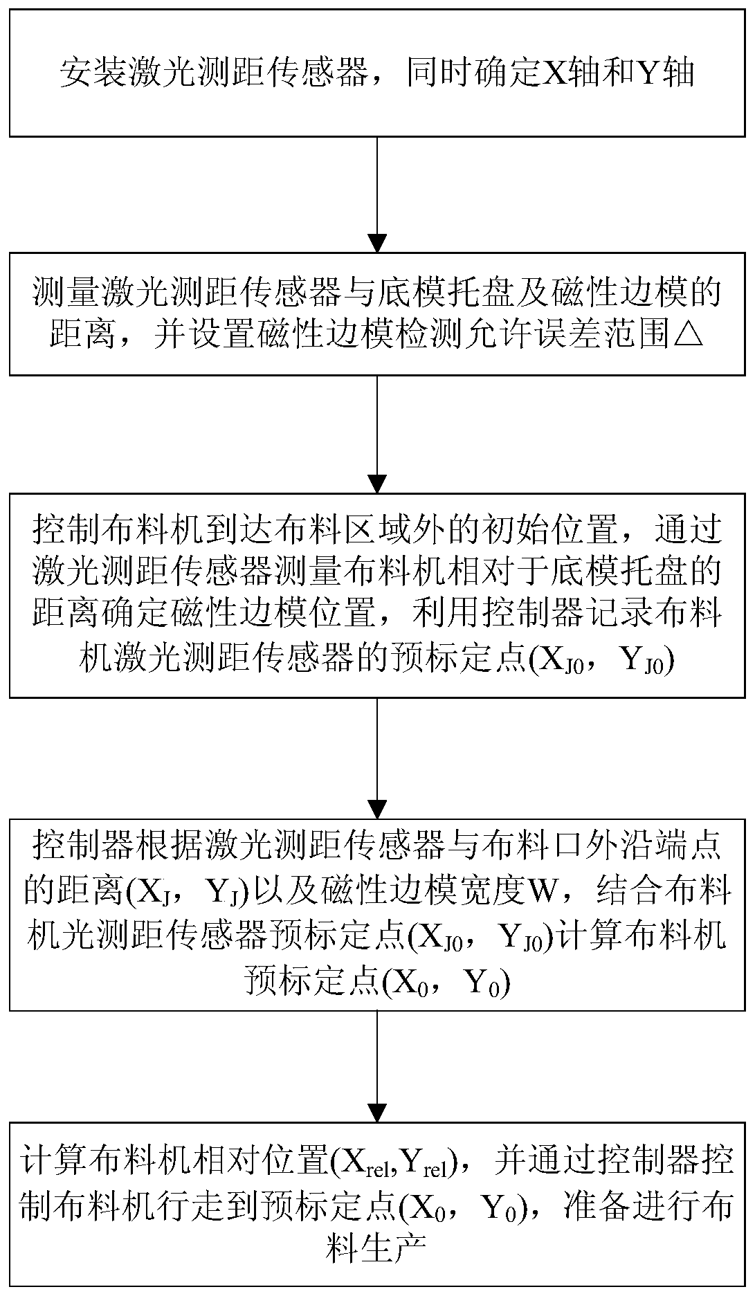
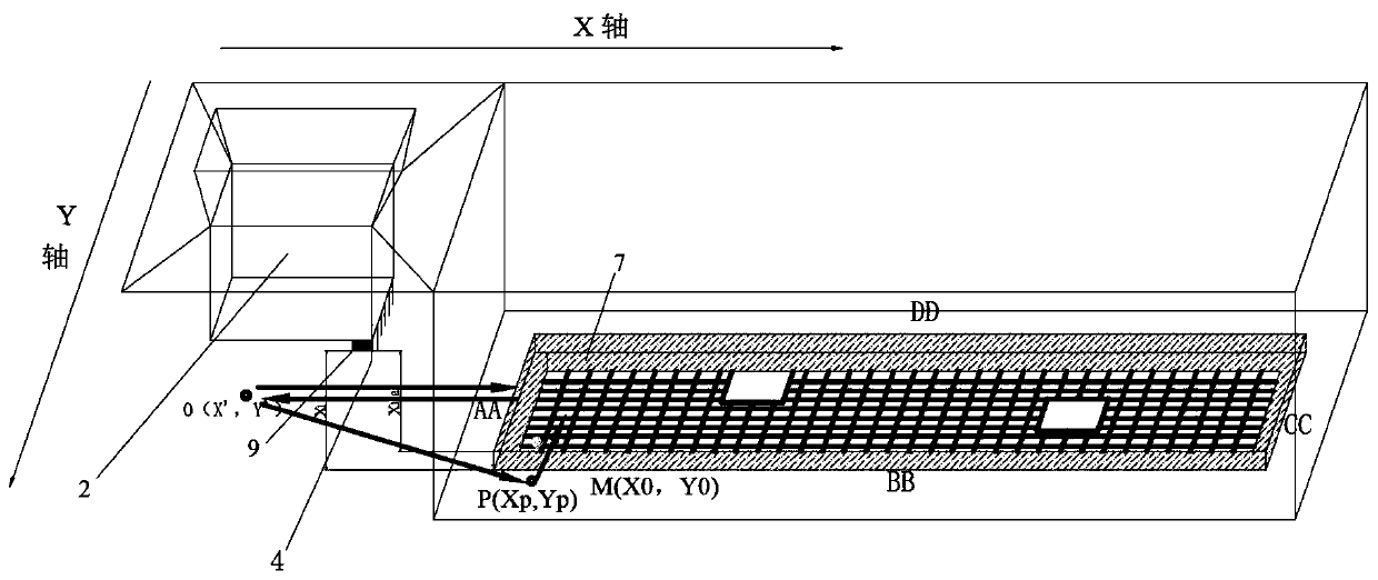
[0025] An automatic pre-calibration method for concrete placing machine based on laser ranging, the process is as follows figure 2 As shown, the principle is as image 3 as shown, image 3 The arrow in indicates the movement route of the controller driving the distribution machine. The specific method is as follows:

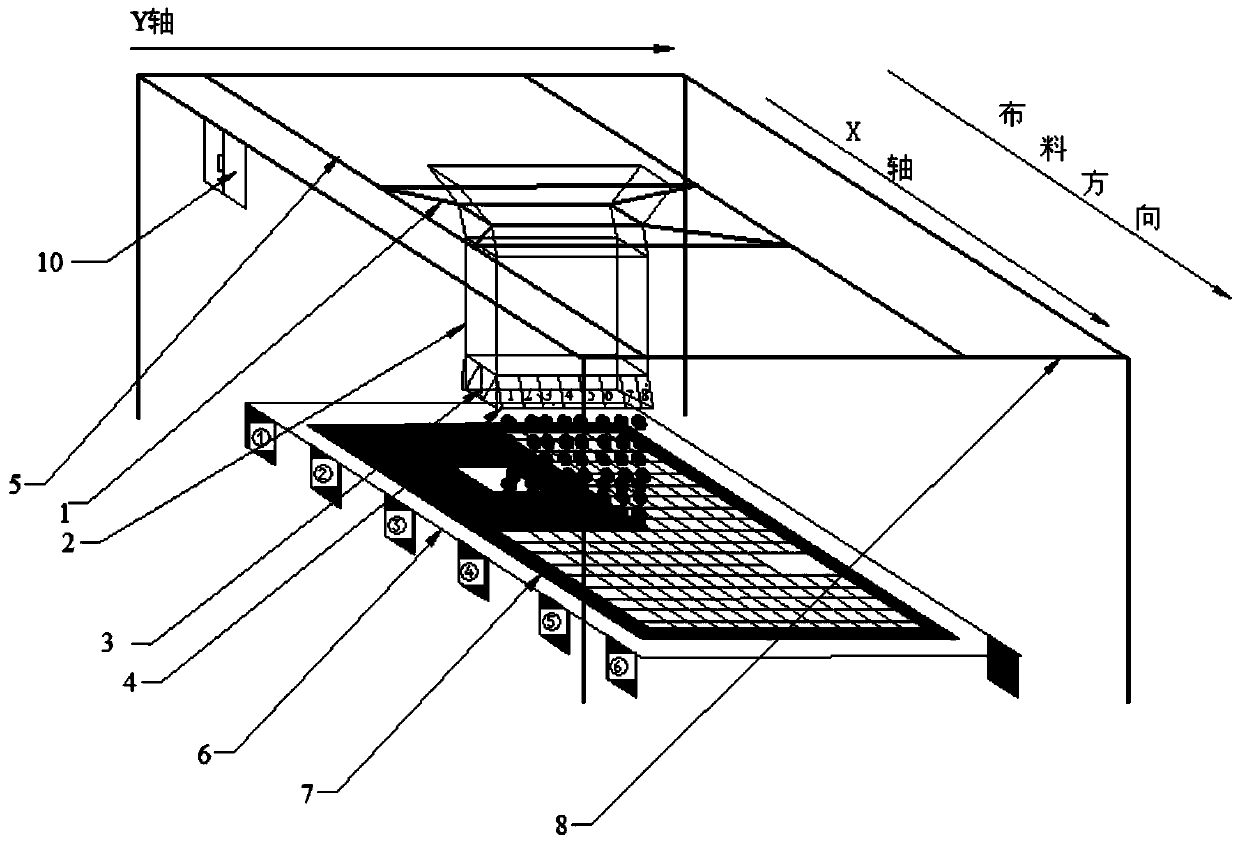
[0026] Step 1: Add a laser distance measuring sensor under the No. 1 cloth opening of the cloth machine. At the same time, the direction parallel to the walking route of the cloth trolley of the cloth machine is defined as the X axis, and the direction perpendicular to the X axis is the Y axis. The ...


PUM


Abstract

The invention provides a concrete distributor automatic pre-calibration method based on laser ranging, and relates to the field of automatic control of prefabricated component concrete distributors inbuilding industrialization. The method comprises the steps that a laser distance sensor is mounted, and meanwhile the axis X and the axis Y are determined; the distance between the laser distance sensor and a bottom mold tray and the distance between the laser distance sensor and a magnetic side mold are measured, and the permissible error range is set; the initial position that a distributor arrives at the position outside a distribution area is controlled, and a controller is utilized for recording the pre-calibration point of the laser distance sensor of the distributor; the pre-calibration point of the distributor is calculated by the controller; and the relative position of the distributor is calculated, the distributor is controlled by the controller to move to the pre-calibration point, and distribution production is prepared. According to the method, modification to existing equipment and detection systems is small, the modification cost is low, compatibility with existing distribution systems is good, and operation is easy to implement; and meanwhile, pre-calibration of the distributor can be completed automatically, and the accuracy that the concrete distributor determines the pre-calibration point and the pre-calibration efficiency can be improved.

Description

technical field [0001] The invention relates to the technical field of automatic control of prefabricated component concrete distribution machines in building industrialization, in particular to an automatic pre-calibration method for concrete distribution machines based on laser distance measurement. Background technique [0002] The concrete placing machine is the key equipment for the factory production of concrete prefabricated components. The higher the level of automation, the shorter the production time of the concrete placing machine, which is more helpful to improve the production efficiency of prefabricated components and reduce and save human resource investment. The pre-calibration technology of the concrete placing machine mainly adopts an automatic method, by finding the position of the magnetic side formwork on the bottom mold tray to determine the starting point of the placing machine to start laying, and then enabling the placing machine control system to con...

Claims


Application Information

Patent Timeline
Patent Type & Authority Patents(China)
IPC IPC(8): B28B13/02B28B17/00G01B11/00G01B11/14
CPCB28B13/026B28B17/0081G01B11/00G01B11/14
Inventor 张珂李冬邹德芳于文达李洋
Owner SHENYANG JIANZHU UNIVERSITY
Why Eureka
Try Eureka