Cutting method of slicing machine with two spindles instead of three spindles

A cutting method and slicer technology, applied in the direction of fine working devices, manufacturing tools, stone processing equipment, etc., can solve the problems of large wire consumption, consumption, and high cost ratio of diamond wire, so as to reduce the number of bending times and reduce the breakage The effect of line risk

Inactive Publication Date: 2019-02-01
SHANGHAI SHENHE THERMO MAGNETICS ELECTRONICS CO LTD
View PDF19 Cites 0 Cited by
  • Summary
  • Abstract
  • Description
  • Claims
  • Application Information

AI Technical Summary

Problems solved by technology

[0003] The cost of diamond wire accounts for a relatively high proportion of the cutting cost. The amount of wire used per wafer is directly related to the cost of silicon wafer cutting. The original method of slicing is to use the three-axis winding mode for cutting. The three-axis winding mode is the above two wires on the same plane. The main shaft and the lower main shaft are in a triangular state. The

Method used


Image

  • Cutting method of slicing machine with two spindles instead of three spindles
  • Cutting method of slicing machine with two spindles instead of three spindles
  • Cutting method of slicing machine with two spindles instead of three spindles

Examples


Embodiment Construction

[0045] The present invention will be further described below in conjunction with the accompanying drawings.

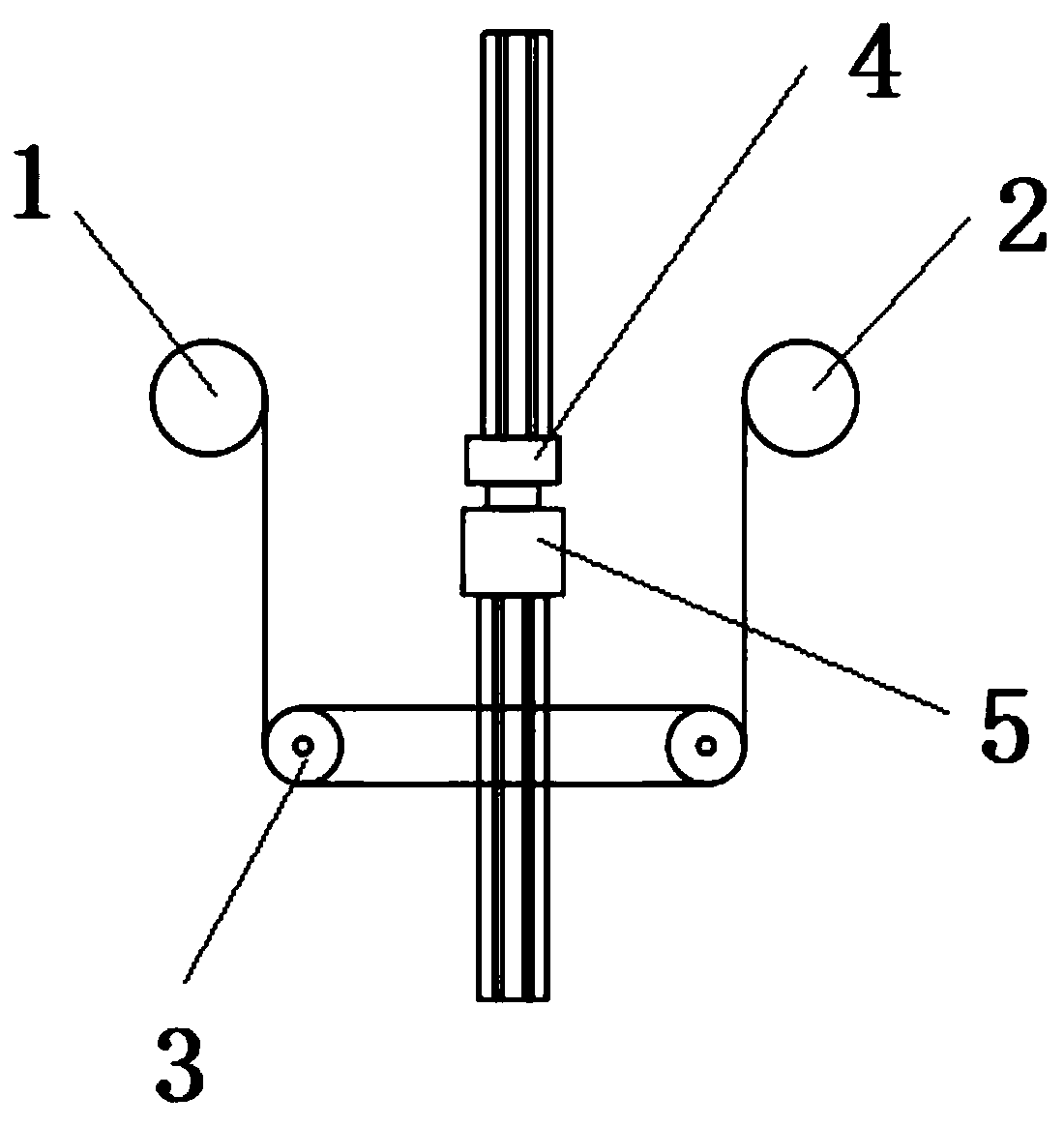
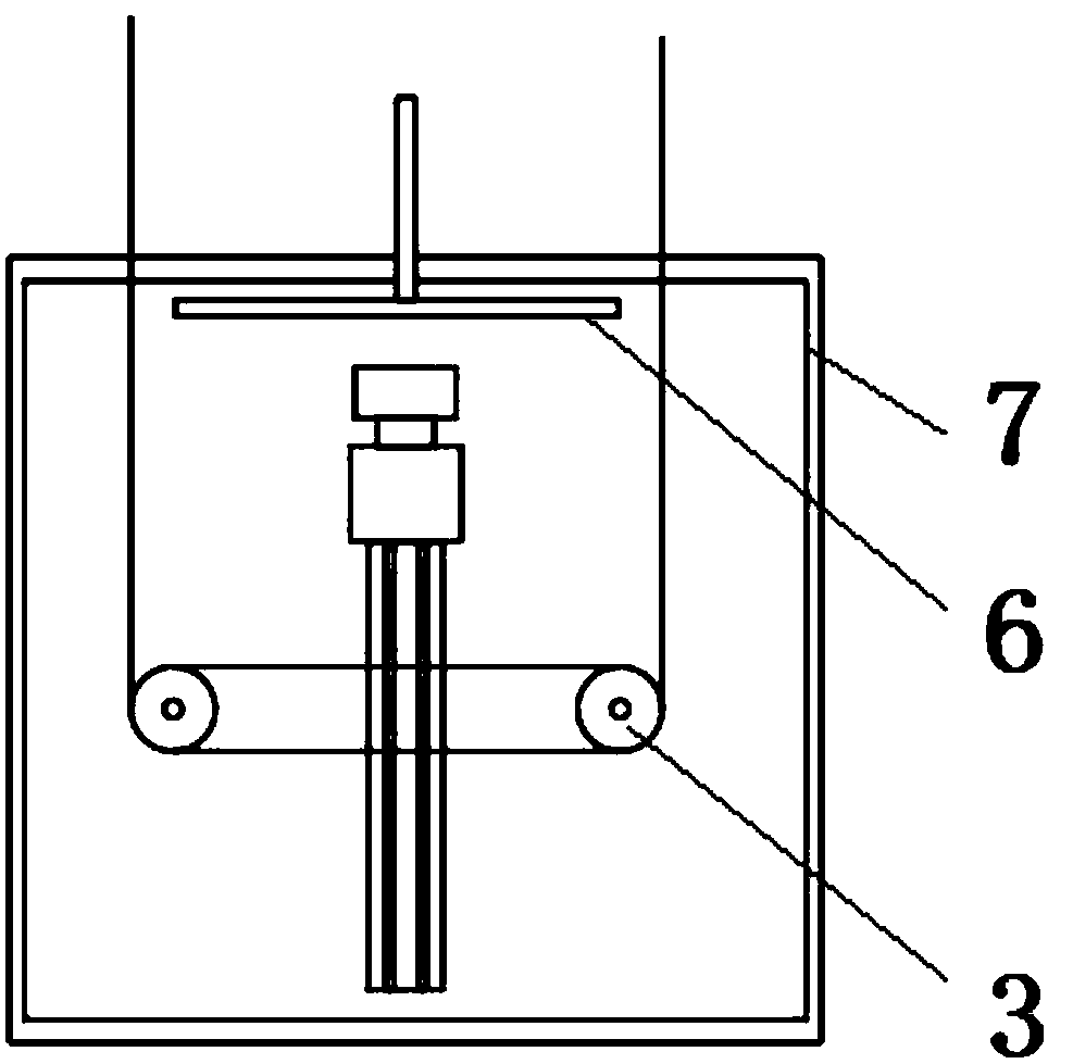
[0046] see Figure 1 to Figure 2 , a three-axis to two-axis slicer cutting method, comprising the following steps: Step 1, winding the diamond wire on the slicer; the slicer includes a driving mechanism for driving the movement of the gold wire, and the driving mechanism includes a pay-off roller 1. Two parallel spindles 3 and take-up roller 2, the diamond wire passes through the pay-off roller 1, the two spindles 3 and the take-up roller 2 in sequence, and the two ends of the diamond wire are respectively fixed with the pay-off roller 1 and the take-up roller 2. The part of the diamond wire wound on the two spindles 3 constitutes a wire mesh for cutting silicon ingots. The length of the wire mesh is 3.6km-4km; step 2, clamping and fixing the silicon ingots on a silicon ingot holder On the holding mechanism 5, the silicon ingot holding mechanism 5 is installed on a ve...


PUM

PropertyMeasurementUnit
Wire diameteraaaaaaaaaa
Diameteraaaaaaaaaa

Abstract

The invention relates to the technical field of semiconductor machining. A cutting method of a slicing machine with two spindles instead of three spindles includes the following steps that (1) steel wires are winded on the slicing machine, the slicing machine comprises a driving mechanism used for driving steel wires to move, the driving mechanism comprises an unwinding roller, the two parallelly-arranged spindles and a winding roller, the steel wires sequentially pass through the unwinding roller, the two spindles and the winding roller, the two ends of the steel wires are fixed to the unwinding roller and the winding roller correspondingly, the portions, winded on the two spindles, of the steel wires form a wire net which is used for cutting silicon ingots; (2) the silicon ingots are clamped and fixed to a silicon ingot clamping mechanism, and the silicon ingot clamping mechanism is mounted on a translation mechanism; and (3) the driving mechanism drives the steel wires to move, andthe translation mechanism drives crystal ingots to move towards the wire net for down-pressing till the crystal ingots are cut into several pieces by the wire net. The slicing machine with the two spindles is adopted for cutting, the consumption of the wires which are densely distributed on the whole wire net is lowered by 15%-20%, and the wire consumption of a single silicon slice is greatly lowered.

Description

technical field [0001] The invention relates to the technical field of semiconductor processing, in particular to a silicon ingot cutting method. Background technique [0002] The production of crystalline silicon solar modules includes crystalline silicon production, ingot casting / pulling, slicing, cell production and module production. Since the current cost of solar silicon wafer power generation is still high, it has no competitive advantage compared with traditional energy sources, so it wants to develop The solar power generation industry needs to reduce costs in all aspects to achieve photovoltaic parity. The slicing link is the process of cutting the silicon ingot into thin slices. The slicing is to bring the SIC abrasive into the processing area (silicon rod) through the high-speed reciprocating motion of the metal wire for grinding, and the diamond wire is to attach the diamond to the steel wire through electroplating technology. cutting. Compared with traditiona...

Claims


Application Information

Patent Timeline
IPC IPC(8): B28D5/00B28D5/04
CPCB28D5/0058B28D5/0082B28D5/045
Inventor 蔡健华贺贤汉许伟伟
Owner SHANGHAI SHENHE THERMO MAGNETICS ELECTRONICS CO LTD
Why Eureka
Try Eureka