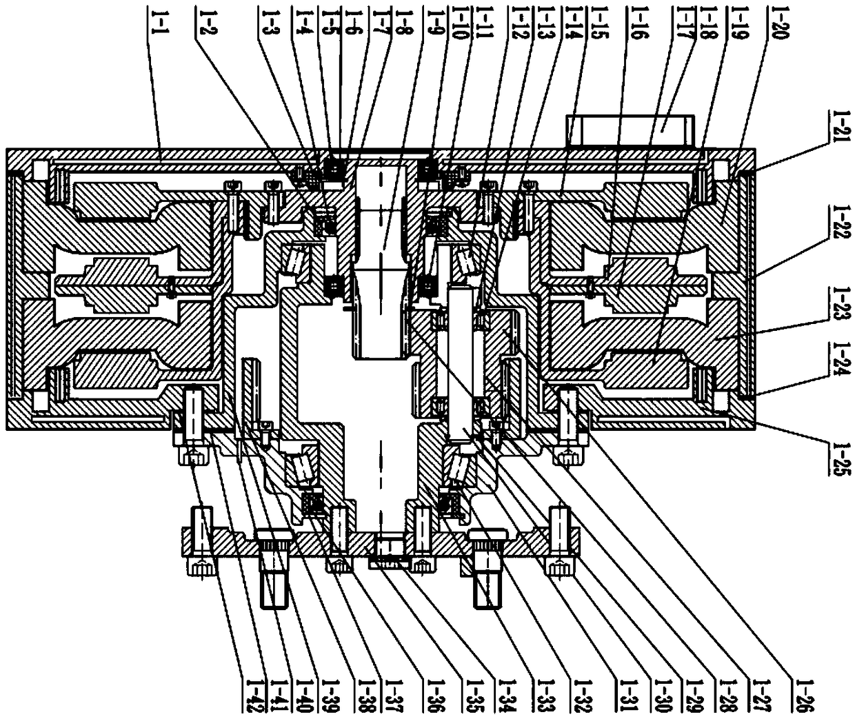
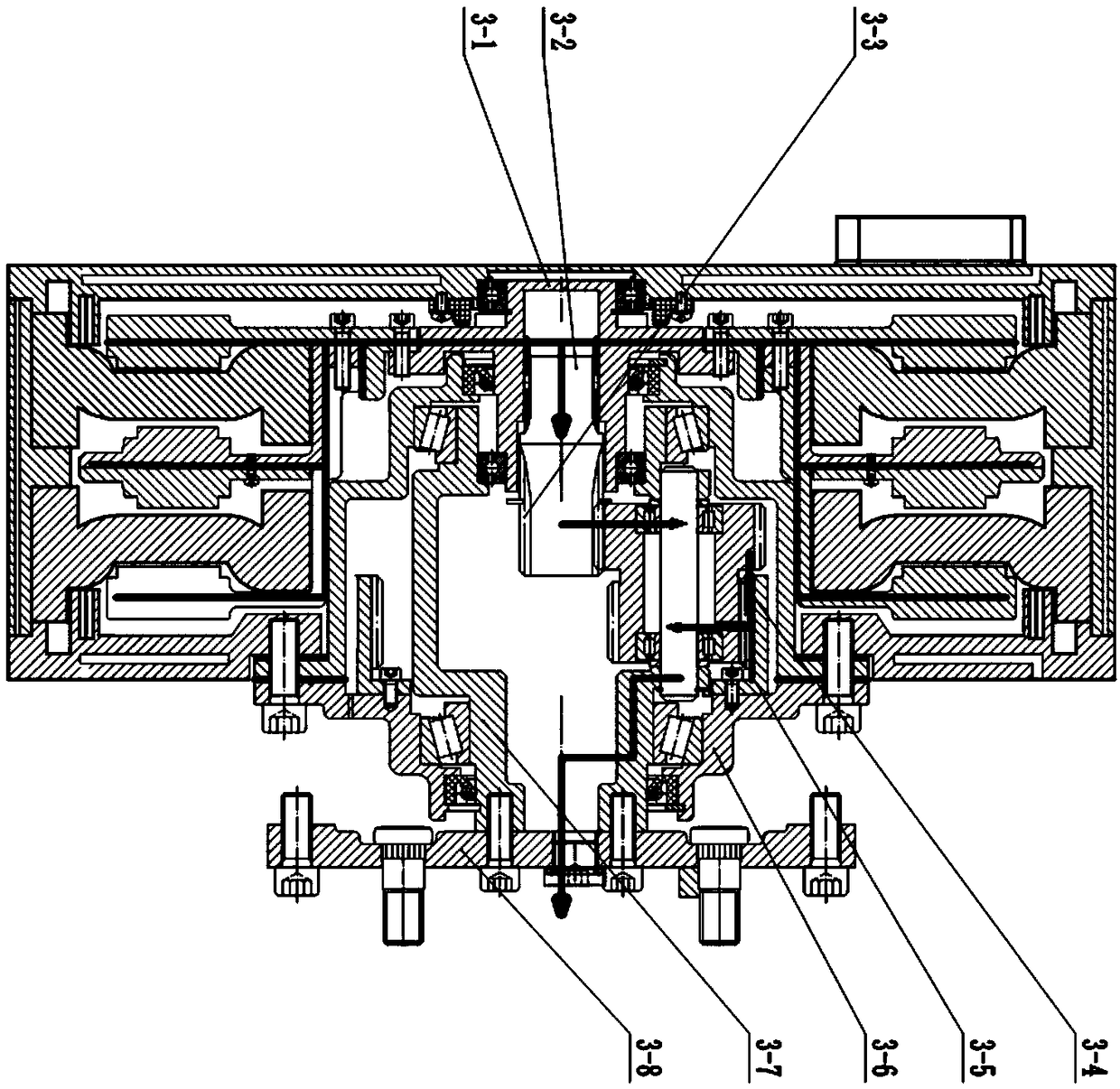
Motor assembly system with built-in speed reducer

A reducer and assembly technology, applied in the field of motor assembly system, can solve problems such as unstable working conditions, reduced reliability, and harsh working environment of hub motors, so as to improve controllability and stability, reduce axial size, Improve the cooling effect

Pending Publication Date: 2019-02-01
武汉一思一得汽车科技有限公司
View PDF7 Cites 8 Cited by
  • Summary
  • Abstract
  • Description
  • Claims
  • Application Information

AI Technical Summary

Problems solved by technology

Most of the existing technical solutions make the motor and the reducer into independent transmission. The disadvantage is that it occupies a large working space. Under some conditions with high requirements for actual space, this independent transmission solution is greatly limited.
[0006] (2) For vehicles driven by in-wheel motors, in-wheel motors and reducers are located inside the wheels, which belong to the unsprung mass. The existing integration of the inner rotor high-speed motor and the wheel-side reducer with independent in-wheel motors inevitably increases the unsprung mass. The increase of the unsprung mass greatly reduces the handling and stability of the vehicle, and also affects the acceleration performance of the vehicle to a certain extent. Therefore, reducing the increase of the unsprung mass caused by the integrated system of the hub motor is the current application research of the hub motor core direction
[0007] (3) For vehicles driven by in-wheel motors, due to the unstable working conditions of the in-wheel motors, harsh working environment, and poor heat dissipation conditions, it is easy to cause the in-wheel motors to heat up. The heating of the in-wheel motors will seriously affect the working efficiency of the motor and the service life of the motor. Part of the heat will be transferred to the reducer, causing the temperature rise of the reducer lubricating oil, which will affect the transmission efficiency of the reducer and the service life of the reducer lubricating oil, increase the maintenance cost of the hub motor assembly, and reduce the reliability
The existing cooling and lubrication methods for hub motor assemblies are independent cooling of the motor shell and independent lubrication of the reducer. This method has great limitations in controlling the temperature of the hub motor assembly, and there is still a lot of room for improvement in its technical methods
[0008] (4) For vehicles driven by in-wheel motors, considering the driving and braking requirements of the vehicle, in addition to the motor and reducer, the in-wheel motor assembly also needs to arrange a braking device. The existing independent transmission method of the

Method used


Image

  • Motor assembly system with built-in speed reducer
  • Motor assembly system with built-in speed reducer
  • Motor assembly system with built-in speed reducer

Examples


Embodiment Construction

[0056] In order to make the object, technical solution and advantages of the present invention more clear, the present invention will be further described in detail below in conjunction with the examples. It should be understood that the specific embodiments described here are only used to explain the present invention, not to limit the present invention.

[0057] For electric drive devices, restricted by actual working conditions, the available space of the system is often small, but the power demand is high, and the driving capacity of the motor is often positively related to its size, volume, and quality, and the volume and mass of the reducer are also related to the transmission capacity. Proportional, obviously, this is contrary to the actual conditions. Most of the existing technical solutions make the motor and the reducer into independent transmission. The disadvantage is that it occupies a large working space. Under some conditions with high requirements for actual sp...


PUM


Abstract

The invention belongs to the technical field of motors and discloses a motor assembly system with a built-in speed reducer. A motor comprises a motor body and a speed reducer; the speed reducer is built in a cavity of the motor; a motor rotor spline sleeve is connected with an input shaft of the speed reducer; and an output shaft of the speed reducer is connected with a working machine. The motorassembly system with the built-in speed reducer has the advantages that the torque density is high, the power density is high, the power transmission capacity is high, the structure is compact, the floor space is small, and the motor assembly system with the built-in speed reducer is suitable for electric driven vehicles and other power equipment with large reduction ratio. The motor assembly system with the built-in speed reducer has the advantages that the transmission efficiency is high, the structure is compact, the power density is high, the torque density is high, and the motor assemblysystem with the built-in speed reducer is suitable for various electric driving devices.

Description

technical field [0001] The invention belongs to the technical field of motors, and in particular relates to a motor assembly system with a built-in reducer. Background technique [0002] At present, the existing technologies commonly used in the industry are as follows: [0003] Due to the outstanding characteristics of large-scale centralized production, long-distance economic transmission, and intelligent automatic control, electric energy has become the main energy source for human production and activities. Correspondingly, the application of electric drive devices is becoming more and more extensive. The motor is the power component of the electric drive device. It has a series of advantages such as high working efficiency, no pollution to the environment, low working noise, convenient use and control, reliable operation, low price, and firm structure. Therefore, it is used in industrial and agricultural production, transportation, Widely used in national defense, comm...

Claims


Application Information

Patent Timeline
IPC IPC(8): B60K7/00B60K17/04H02K7/116
CPCH02K7/116B60K7/0007B60K17/046B60K2007/0092
Inventor 吴森付翔刘中林
Owner 武汉一思一得汽车科技有限公司
Why Eureka
Try Eureka