Tunneling method and system for automatic surveying, mapping and positioning

An automatic and roadheader technology, which is applied in the direction of earth drilling, mining equipment, cutting machinery, etc., can solve the problem of intelligent and unmanned excavation, automatic measurement of underground space, accurate positioning of construction equipment, and real-time modeling of excavation space And visualization, aerospace navigation locator can not be used directly, etc., to achieve the effect of reliable design principle, wide application prospects, and accurate positioning

Active Publication Date: 2019-02-01
山东蓝光软件有限公司
View PDF6 Cites 12 Cited by
  • Summary
  • Abstract
  • Description
  • Claims
  • Application Information

AI Technical Summary

Problems solved by technology

[0003] At present, the intelligent cantilever tunnel boring machine is the most used in mines. Although this tunnel boring machine can realize automatic control, it has not realized the automatic measurement of underground space, the precise positioning of construction equipment and the real-time modeling and visualization of excavation space. , it is impossible to realize the complete automation and unmanned operation of underground excavation engineering, which seriously affects the technological progress of intelligent excavation engineering
Although the invention patent with the publication number CN101169038A and the name of the fully automatic roadh

Method used


Image

  • Tunneling method and system for automatic surveying, mapping and positioning
  • Tunneling method and system for automatic surveying, mapping and positioning
  • Tunneling method and system for automatic surveying, mapping and positioning

Examples


Embodiment Construction

[0062] In order to enable those skilled in the art to better understand the technical solutions in the present invention, the technical solutions in the embodiments of the present invention will be clearly and completely described below in conjunction with the drawings in the embodiments of the present invention. Obviously, the described The embodiments are only some of the embodiments of the present invention, not all of them. Based on the embodiments of the present invention, all other embodiments obtained by persons of ordinary skill in the art without making creative efforts shall fall within the protection scope of the present invention.

[0063] Key terms appearing in this application are explained below.

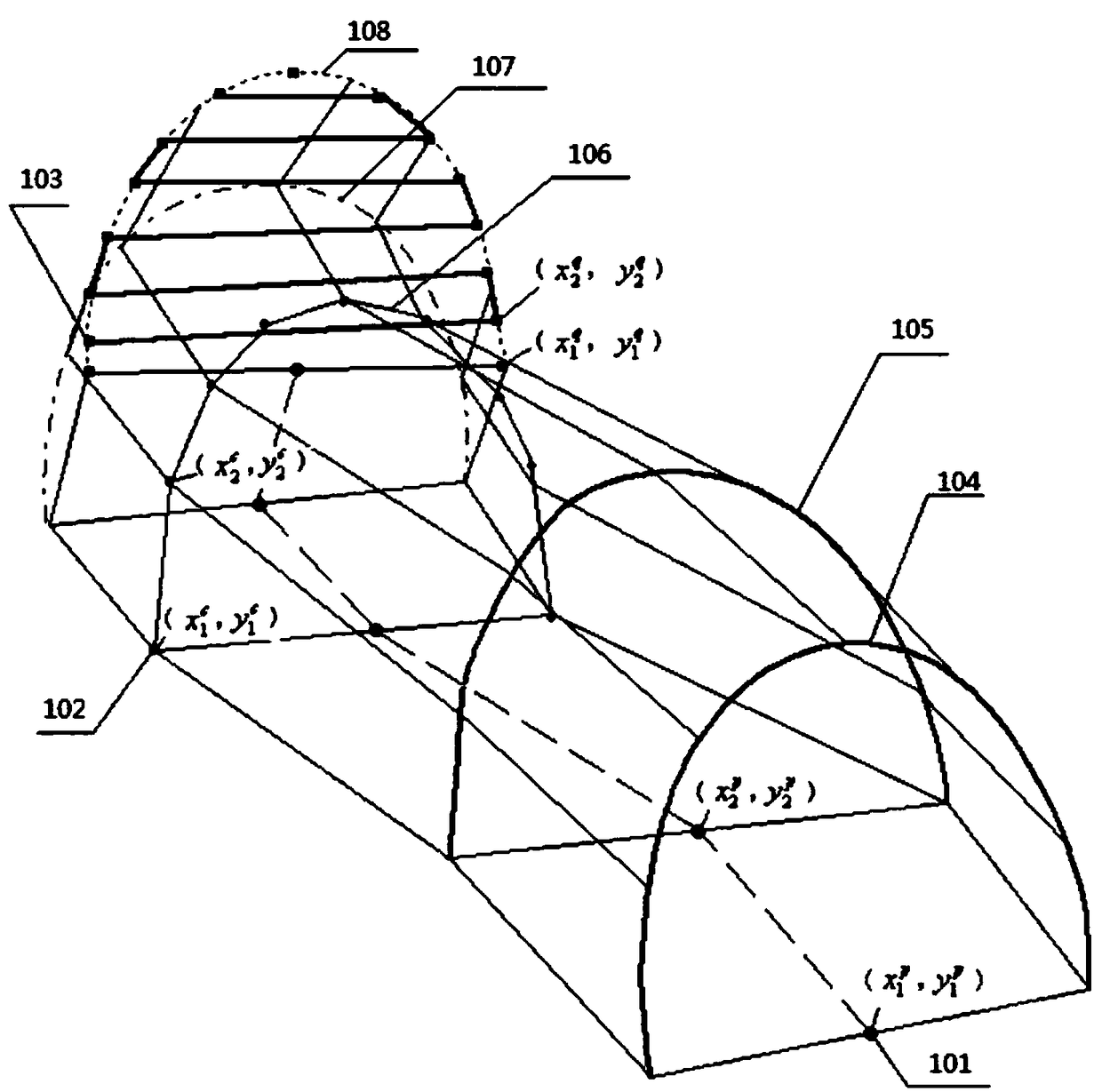
[0064] Such as figure 1 As shown, the excavation method 100 for automatic surveying and positioning provided by the present application includes:

[0065] Step 110, discretizing the shaft model given by the design system into a polyline of the central axis of the bo...


PUM


Abstract

The invention provides a tunneling method and system for automatic surveying, mapping and positioning. The tunneling method comprise the steps that a well lane model given by a design system is dispersed into a bottom plate middle axis multi-section line and a well lane section contour polygon; a machine body coordinate system of a heading machine is set with the right side direction of the heading machine as the X axis, the head direction of the heading machine as the Y axis, and perpendicular to the XOY plane and the overall upward direction as the Z axis; the relative position coordinate increment from the laser target ball position to the turning center of the heading machine is calibrated according to the coordinate axis increment of the machine body coordinate system; the position coordinates of a laser target ball of the heading machine are positioned by using a positioning robot and a north pointing device; according to the position coordinate of the laser target ball and the relative position coordinate increment of the laser target ball position in the machine body coordinate system, the motion base point coordinates of a cantilever of the heading machine is calculated; the heading machine is controlled to cut the radial section according to the multi-section line of the bottom middle axis, the well lane section contour polygon, and the motion base point coordinates of the cantilever of the heading machine. According to the tunneling method and system, the heading machine can be accurately positioned, and the operation is unmanned.

Description

technical field [0001] The invention belongs to the technical field of automatic tunneling in shafts, and in particular relates to a tunneling method and system for automatic surveying, mapping and positioning. Background technique [0002] No matter it is the tunnel excavation of mining engineering, the tunnel excavation of road engineering, or the culvert excavation of water conservancy engineering, it is a difficult construction project. In addition, affected by complex geological conditions and geological disasters, casualties occur from time to time. The operation is not only labor-intensive and construction efficiency is low, but also personal safety and health are difficult to guarantee. Therefore, various auxiliary excavation construction machines have emerged, such as roadheaders, continuous mining machines, shield machines, rock drills, etc., and some machines have been transformed into intelligent equipment capable of remote control. [0003] At present, the inte...

Claims


Application Information

Patent Timeline
IPC IPC(8): E21D9/00E21D9/10E21C35/08E21C35/24
CPCE21C35/08E21C35/24E21D9/003E21D9/108
Inventor 卢新明尹红
Owner 山东蓝光软件有限公司
Why Eureka
Try Eureka