Air distribution structure of low-temperature rotational-flow rotary-disc material drying machine
A drying machine and air distribution technology, which is applied in the direction of drying machines, drying solid materials, and drying gas layout, etc., can solve the problems of single hot air direction, increase hot air volume, and reduce production efficiency, so as to increase the contact area and strengthen Effect of heat transfer and reduction of hot air volume
- Summary
- Abstract
- Description
- Claims
- Application Information
AI Technical Summary
Problems solved by technology
Method used
Image
Examples
Embodiment 1
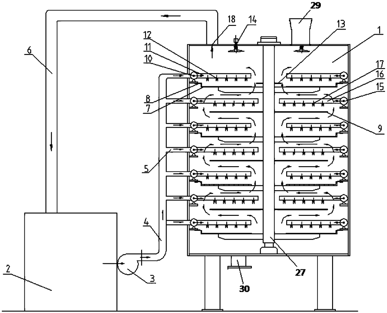
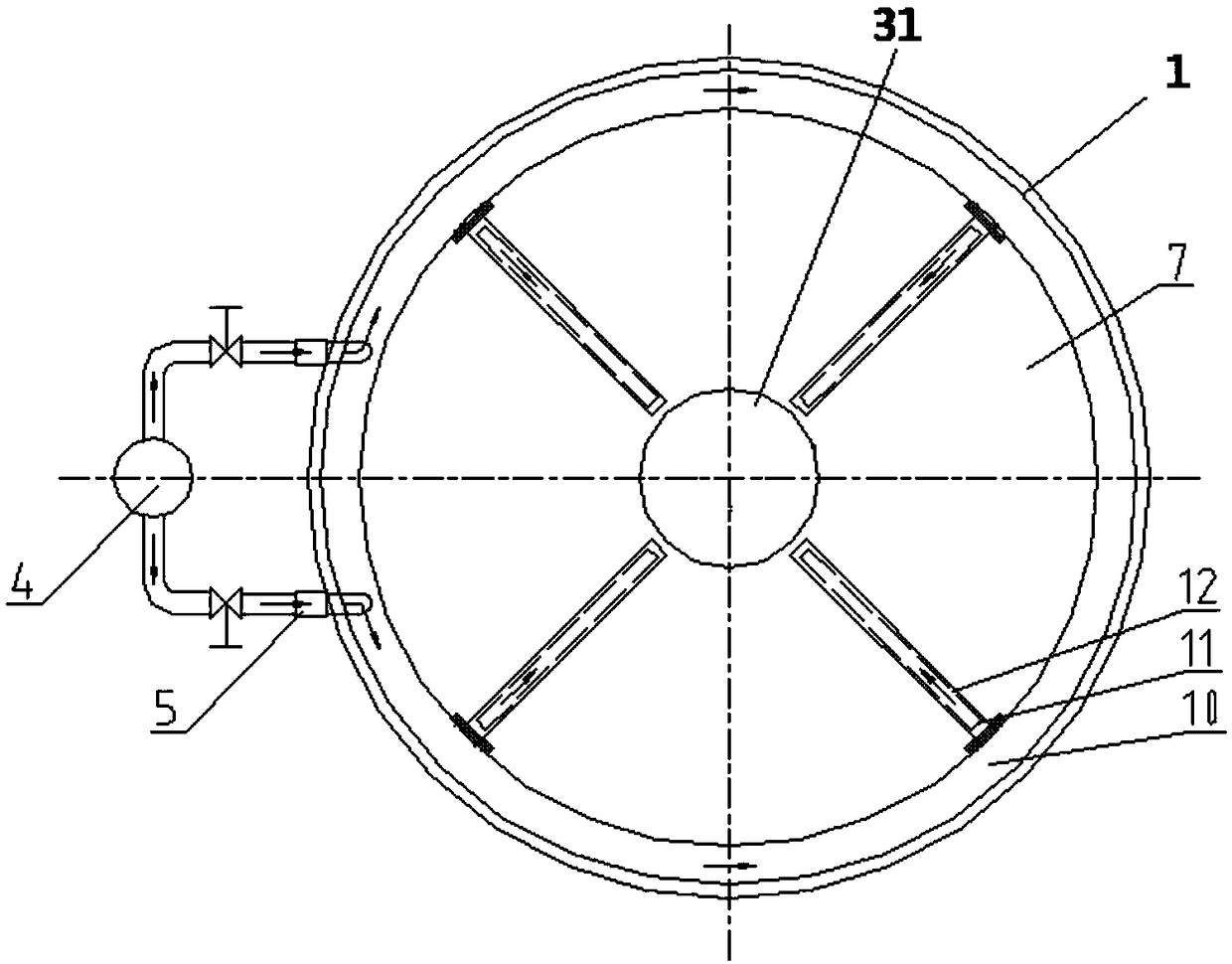
[0031] like Figure 1a As shown, the material drying machine of the present invention includes a drying chamber 1, a heat pump 2, a blower 3, an air supply duct 4, an air distribution duct 5 and a return air duct 6, wherein the drying chamber 1 is surrounded by a large material tray 7 and a small material The tray 9 is divided into a multi-layer structure. The large tray 7 is provided with a large tray air ring 10 along the inner wall of the drying chamber 1 above the large tray 7. The small tray 9 is provided along the inner wall of the drying chamber 1. A small tray air ring 15 , the air distribution ring 10 of the large material plate and the air distribution ring 15 of the small material plate are respectively communicated with the air outlet of the heat pump 2 through the air supply pipe 4 and the air distribution pipe 5 . The large pan air ducts 11 extending into the drying chamber 1 are evenly distributed on the large pan air distribution ring 10 . The air distribution ...
Embodiment 2
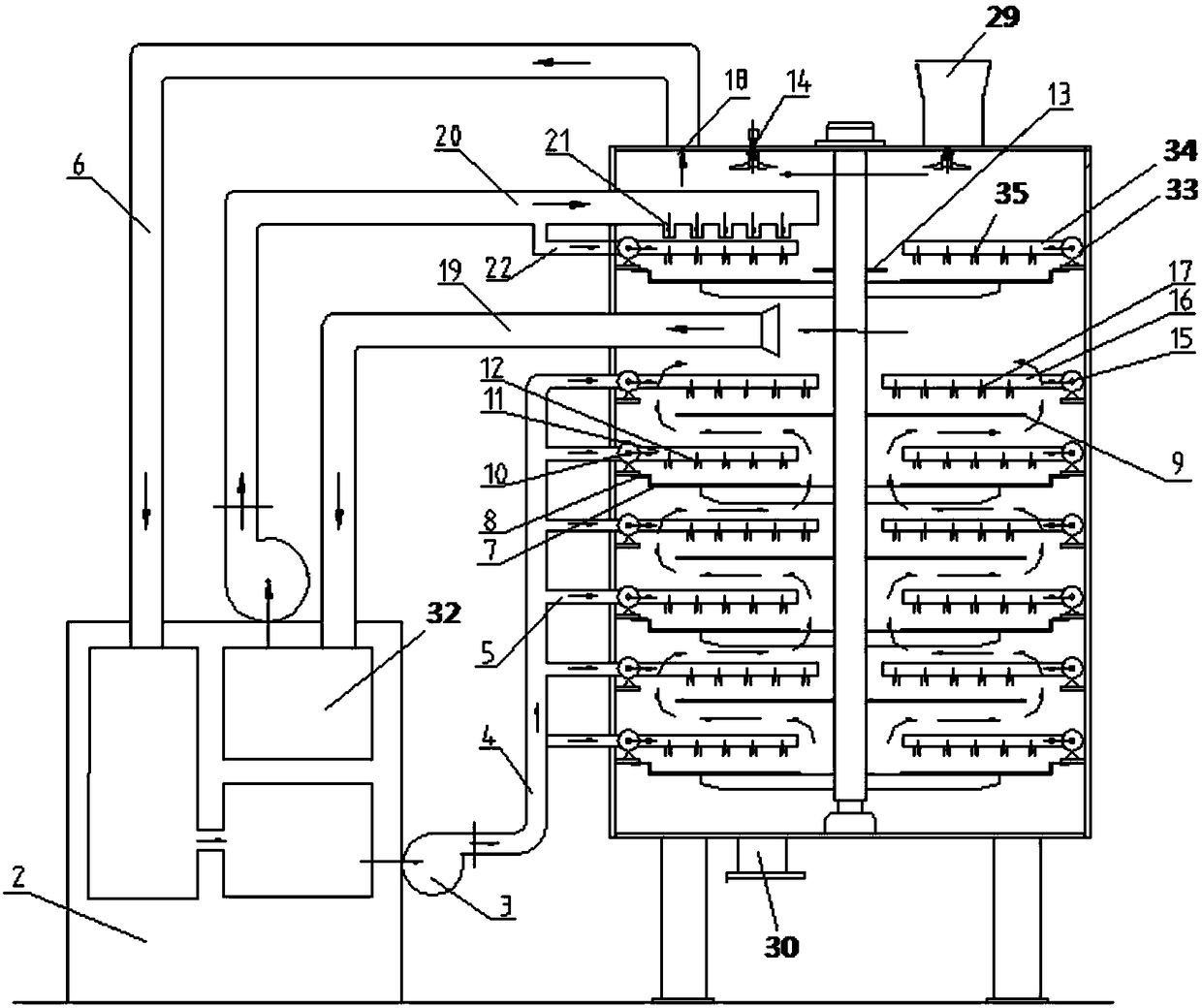
[0044] like Figure 1b As shown in the figure, the difference between this embodiment and Embodiment 1 is that the feeding trays arranged step by step in the drying chamber 1 are divided into an upper feeding tray and a lower feeding tray, and the upper feeding tray is connected to the reheating work heated by the reheating circuit. The gas purges the upper wet material to compensate for the problem that the gas temperature in the upper tray is too low. Specifically, it includes a heat pump reheater 32 , a reheat return air pipe 19 , a reheat air supply pipe 22 , a reheat air distribution ring 33 , a reheat air distribution pipe 34 , and a reheat air distribution port 35 . The heat pump reheater 32 can be integrated in the heat pump 2 or independent of the heat pump 2. The air inlet of the reheat return air pipe 19 is arranged between the upper and lower material pans, and the air outlet is connected to the heat pump reheater. 32 air inlets.
[0045] One end of the reheat ai...
Embodiment 3
[0048] The difference between this embodiment and Embodiments 1 and 2 is that the first rake arm 23 and the inner push rake teeth 24 and between the second rake arm 25 and the outer expansion rake teeth 26 can be relatively movable, that is, the rake teeth are sleeved on the On the rake arm, it is not stuck and can swing freely along the rake arm, and the angles of the rake teeth on the two adjacent layers of material trays are opposite.
[0049] At the same time, the first rake arm 23 and the second rake arm 25 are hollow structures, and the first rake arm 23 and the second rake arm 25 are respectively connected with the air distribution ring 10 of the large material tray and the air distribution ring 15 of the small material tray. Where the arm 23 faces the large feeding tray 7 is provided with the large feeding tray tuyere 12 , and the second rake arm 25 faces the small feeding tray 9 is provided with the small feeding tray tuyere 17 .
[0050] In this embodiment, preferabl...
PUM
 Abstract
Description
Claims
Application Information
 - R&D
- Intellectual Property
- Life Sciences
- Materials
- Tech Scout
- Unparalleled Data Quality
- Higher Quality Content
- 60% Fewer Hallucinations
Browse by: Latest US Patents, China's latest patents, Technical Efficacy Thesaurus, Application Domain, Technology Topic, Popular Technical Reports.
© 2025 PatSnap. All rights reserved.Legal|Privacy policy|Modern Slavery Act Transparency Statement|Sitemap|About US| Contact US: help@patsnap.com


