
A positioning floor, positioning system and positioning method

A positioning system and floor technology, applied in positioning, radio wave measurement system, service based on location information, etc., can solve problems affecting safety and aesthetics, signal overlap or cross-reading, weak current construction time-consuming and labor-intensive, etc., to achieve positioning Improved accuracy and anti-interference ability, improved positioning accuracy, and the effect of low-frequency signal concentration

Active Publication Date: 2021-01-08
BEIJING KINGDOES RFID TECH
View PDF6 Cites 0 Cited by
  • Summary
  • Abstract
  • Description
  • Claims
  • Application Information

AI Technical Summary

Problems solved by technology

[0004] At present, the relatively mature RFID technology applied to indoor personnel or object positioning adopts dual-frequency (125KHz low-frequency + 2.4GHz active) trigger scheme to realize, but this technical scheme needs to carry out complicated weak current construction stage, for example, in the use of ceiling-mounted When positioning the antenna, it is necessary to lay the power line for the low-frequency activator on the ceiling and reserve the interface. If there are many positioning antennas and many activators are used, the weak current construction will be extremely time-consuming; To carry out large-scale renovation of the indoor floor, the concrete floor needs to be cut to embed the antenna, and the ceramic tile, wooden floor, and anti-static floor all need to replace or renovate the floor. These tasks are time-consuming and laborious, and will affect their own safety after the renovation Degree and beauty
In addition, when the ceiling-mounted positioning antenna is used, since the positioning antenna is installed on the ceiling, the signal radiation range is relatively wide, and it is subject to refraction and interference, and signal overlap or cross-reading is easy to occur, resulting in inaccurate positioning

Method used


Image

  • A positioning floor, positioning system and positioning method
  • A positioning floor, positioning system and positioning method
  • A positioning floor, positioning system and positioning method

Examples


Embodiment Construction

[0037] Specific embodiments of the present invention will be described in detail below, and it should be noted that the embodiments described here are only for illustration, not for limiting the present invention. In the following description, numerous specific details are set forth in order to provide a thorough understanding of the present invention. It will be apparent, however, to one of ordinary skill in the art that these specific details need not be employed to practice the present invention. In other instances, well-known circuits, software or methods have not been described in detail in order not to obscure the present invention.

[0038] Throughout this specification, reference to "one embodiment," "an embodiment," "an example," or "example" means that a particular feature, structure, or characteristic described in connection with the embodiment or example is included in the present invention. In at least one embodiment. Thus, appearances of the phrases "in one emb...


PUM


Abstract

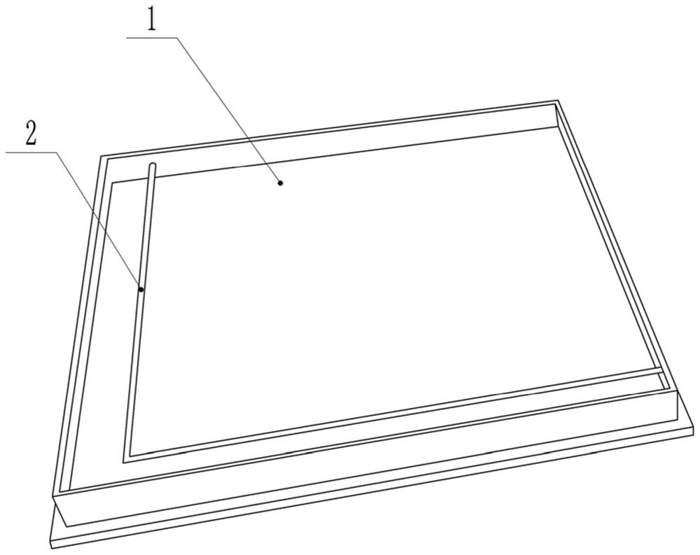
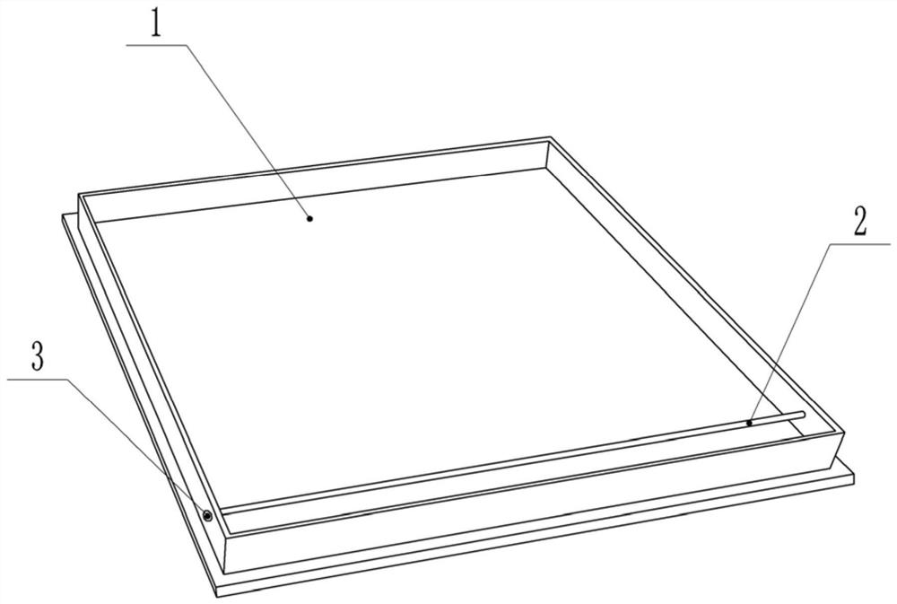
The invention relates to the technical field of RFID (Radio Frequency Identification), in particular to a positioning floor, a positioning system and a positioning method. The positioning floor comprises a floor and a positioning antenna packaged on the floor. The positioning antenna is connected with a signal source, and transmits a low-frequency pulse signal to form a low-frequency activation trigger region. The positioning method provided by the invention comprises the following steps of: presetting the positioning antenna in the low-frequency trigger positioning technology in an anti-static floor, that is, directly using the floor as the positioning antenna, and adjusting the identification range of the positioning antenna by adjusting the number of the splicing floor to control the accuracy of the positioning range. The low-frequency signal is more concentrated and less divergent since the mounting position of the anti-static floor is closer to a positioned tag, and the material characteristics of the anti-static floor can filter the signal of the part of the positioning antenna, therefore, the positioning is more accurate.

Description

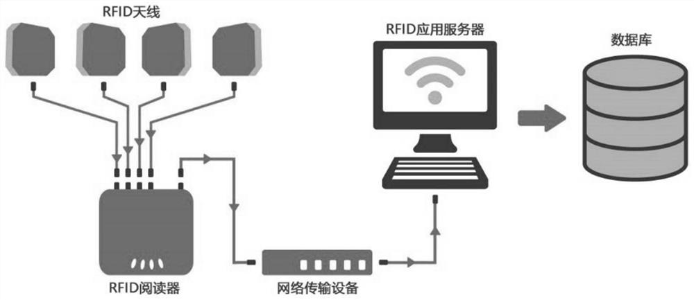
technical field [0001] The invention relates to the field of RFID technology, in particular to a positioning floor, a positioning system and a positioning method. Background technique [0002] RFID (Radio Frequency Identification) is a non-contact automatic identification technology that can identify specific targets and read and write related data through radio signals without establishing mechanical or optical contact between the identification system and specific targets. Because it can read and write quickly and track management goals for a long time, it is widely favored in the field of intelligent identification. At the same time, with the rapid development of the Internet of Things technology in our country, RFID technology as the supporting technology of the Internet of Things is considered to be one of the promising information technologies, such as figure 1 A typical RFID system structure is shown. [0003] In the application of RFID technology, positioning servi...

Claims


Application Information

Patent Timeline
Patent Type & Authority Patents(China)
IPC IPC(8): G01S5/08H04W4/021H04W4/33H04W64/00H01Q1/22H01Q1/36E04F15/02
CPCE04F15/02E04F2290/02E04F2290/048G01S5/08H01Q1/22H01Q1/36H04W4/023H04W64/006H04W4/33
Inventor 张鹏
Owner BEIJING KINGDOES RFID TECH
Learn More