Electronic chip efficient welding equipment

A technology for electronic chips and welding equipment, which is applied in the field of high-efficiency welding equipment for electronic chips, can solve the problems of inconvenient adjustment of the rotation angle of the rotary servo motor, failure of the rotary servo motor, and large size of the welding frame, and achieve good shock absorption and buffering effects. The effect of reducing the volume of the equipment and reducing the cost

Inactive Publication Date: 2019-02-05
CHANGSHA KEYUE ENTERPRISE MANAGEMENT CONSULTING CO LTD
View PDF1 Cites 1 Cited by
  • Summary
  • Abstract
  • Description
  • Claims
  • Application Information

AI Technical Summary

Problems solved by technology

However, the welding frame of this device has a large volume, and it is inconvenient to transport and install. At the same time, the distance between the rotary servo motor and the electronic chip is too close, and the high temperature generated during the welding process is easy to cause the fault of the rotary servo motor. Angle is also very inconvenient

Method used


Image

  • Electronic chip efficient welding equipment
  • Electronic chip efficient welding equipment
  • Electronic chip efficient welding equipment

Examples


Embodiment 1

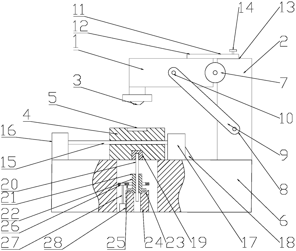
[0016] see figure 1 , a high-efficiency welding equipment for electronic chips, including a welding frame 1, a column 2, a welding head 3, a welding table 4, an electronic chip 5 and a base 6, the column 2 is fixed on the right side of the upper end surface of the base 6 by bolts, and the The welding frame 1 is arranged on the left side of the top of the column 2, the welding head 3 is installed on the left side of the bottom of the welding frame 1, the welding table 4 is arranged directly below the welding head 3, and the welding The electronic chip 5 is arranged on the platform 4, and the welding platform 4 is placed on the base 6; the welding frame 1 is installed on the left side of the top of the column 2 through the rotating shaft 7, and the column 2 is symmetrical front and back The bolt is fixed with hinge A8, and the front and rear symmetrical bolts of the welding frame 1 are fixed with hinge B10. Freely rotate on the column 2 and maintain good stability; the welding ...

Embodiment 2

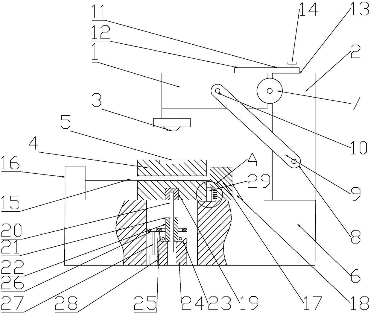
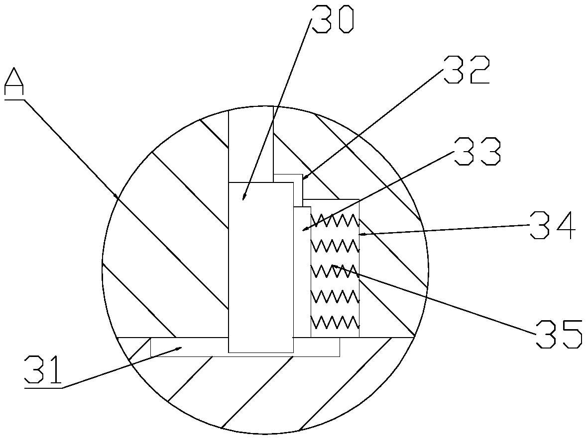
[0018] see figure 2 and image 3 Compared with Embodiment 1, this Embodiment 2 differs only in that a buffer mechanism 29 is provided on the left side of the baffle plate 17, which can have a good shock-absorbing and buffering effect, and avoid contact with the welding table 4 during the sliding process. The impact of the baffle plate 17 causes the reduction of the accuracy of the whole device; the buffer mechanism 29 includes a limiting plate 30, a chute 31, a limiting groove 32, a buffer plate 33, a cavity 34 and a spring 35, and the limiting plate 30 is in contact with the limiting plate 30. The right end surface of the welding table 4 is in close contact, the limiting plate 30 is slidably installed in the limiting groove 32 through the chute 31, a buffer plate 33 is welded and fixed on the right side of the limiting plate 30, the buffering Plate 33 is slidably mounted in said cavity 34 via said spring 35 .

[0019]The working principle of the present invention is: descr...


PUM


Abstract

The invention relates to the technical field of electronic chips, in particular to electronic chip efficient welding equipment. The electronic chip efficient welding equipment comprises a welding machine frame, a vertical column, a welding head, a welding table, an electronic chip and a base; the welding machine frame is rotationally installed on the left side of the top end of the vertical columnthrough a rotary shaft, and the welding machine frame and the vertical column are fixed through a fixing mechanism; a screw rod is installed in the welding table through a thread, the left end of thescrew rod is installed on a driving motor through a key, and the right end of the screw rod is rotationally installed on a baffle; the baffle is welded and fixed to the upper end surface of the base;and a spline shaft sleeve is welded and fixed to the bottom of the welding table and connected with a spline shaft through splines, and the bottom of the spline shaft is provided with a lifting mechanism. The electronic chip efficient welding equipment is simple in structure, low in cost, small in whole size, capable of effectively ensuring the welding precision of the electronic chip, strong inmarket competitiveness and worthy of application and popularization.

Description

technical field [0001] The invention relates to the technical field of electronic chips, in particular to high-efficiency welding equipment for electronic chips. Background technique [0002] Electronic chips, integrated circuits, or microcircuits, microchips, and chips, are a way of miniaturizing circuits (mainly including semiconductor devices, including passive components, etc.) in electronics, and are often manufactured on semiconductor wafers. On the surface. [0003] Chinese patent (notification number: CN104646826A, announcement date: 2015.05.27) discloses an electronic chip welding device, including a frame, an electronic chip, a fixing seat, a first servo motor, a first screw rod, a mobile mounting seat, a laser Welding head, electron microscope, moving seat, rotary servo motor, wire welding machine, second servo motor, second screw rod; through the wire welder, the thin copper wire is conveyed to the electronic chip welding place, and the cathode and anode in the ...

Claims


Application Information

Patent Timeline
Patent Type & Authority Applications(China)
IPC IPC(8): B23K37/047
CPCB23K37/047
Inventor 徐尚
Owner CHANGSHA KEYUE ENTERPRISE MANAGEMENT CONSULTING CO LTD
Why Eureka
Try Eureka