
Pipeline type self-circulation heating decontamination device

A decontamination device and self-circulation technology, applied in lighting and heating equipment, indirect heat exchangers, chemical instruments and methods, etc., can solve problems such as increasing the cost of decontamination solutions, increasing heating costs, consuming coal resources, etc., to avoid Frozen pipes, saving procurement costs, good cleaning effect

Pending Publication Date: 2019-02-12
青岛圣族激光机械有限公司
View PDF0 Cites 2 Cited by
  • Summary
  • Abstract
  • Description
  • Claims
  • Application Information

AI Technical Summary

Problems solved by technology

[0002] As the weather becomes colder and the temperature drops in winter, during the machining process of the product, the surface of the product will be stained with cutting fluid or oil, which is not easy to clean, and the traditional water washing scheme will lead to incomplete cleaning of the oil stain on the stainless steel surface , the cleaning speed is slow, the time becomes longer, and the amount of cleaning solvent is increased, resulting in more cleaning times, wasting water, time and manpower. The current winter decontamination of oily products is to increase the concentration of the decontamination solution and install additional pools. For the heat preservation device, hot water is used for flushing, which increases the cost of the decontamination solution, and the heat preservation device does not play a substantial role. Moreover, the labor cost is increased by boiling water, and a lot of water resources are wasted. At the same time, coal resources are consumed. Increased heating costs

Method used


Image

  • Pipeline type self-circulation heating decontamination device

Examples


Embodiment Construction

[0016] In order to enhance the understanding of the present invention, the present invention will be further described in detail below in conjunction with the accompanying drawings and embodiments, which are only used to explain the present invention and do not limit the protection scope of the present invention.

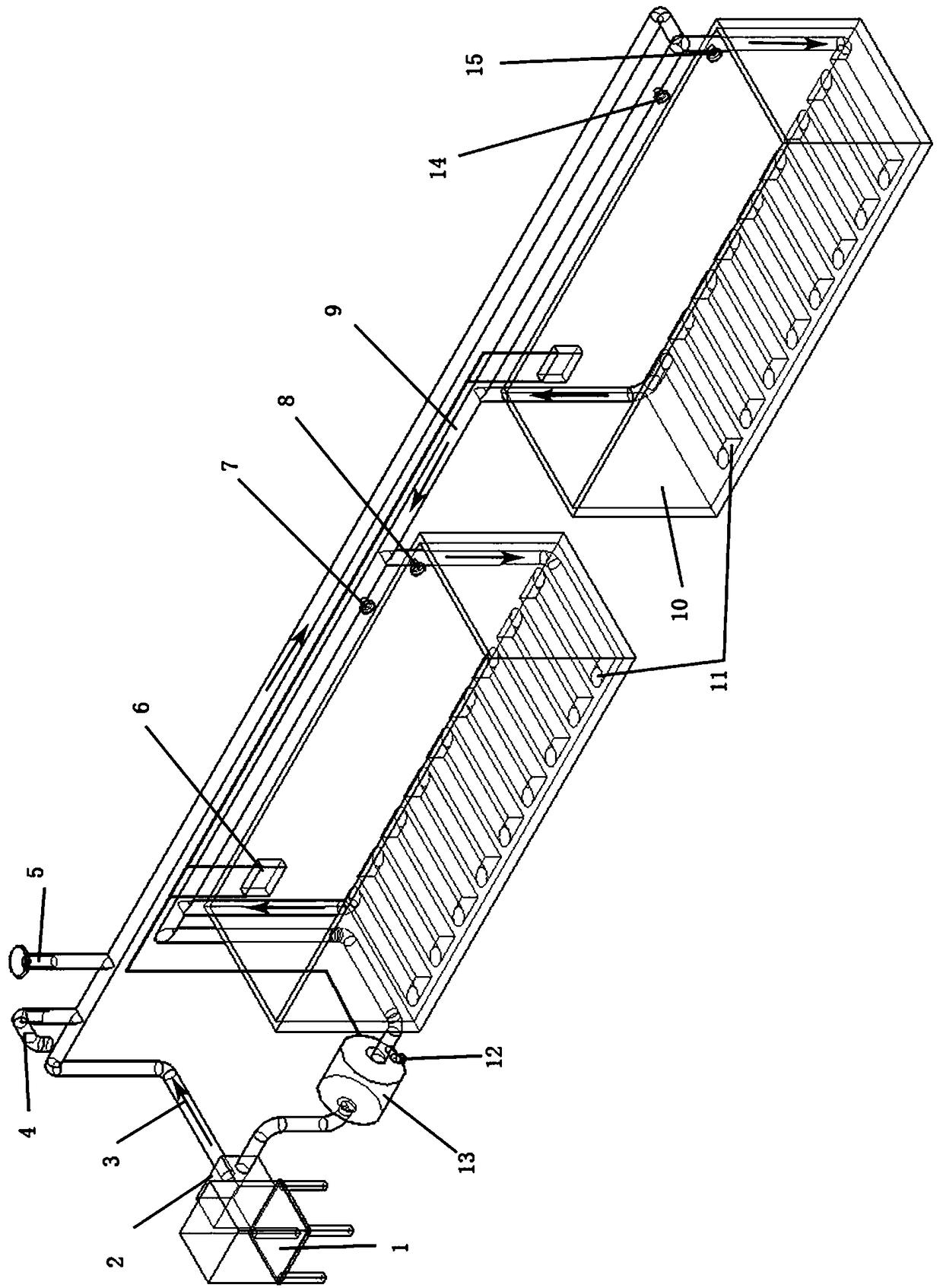
[0017] Such as figure 1 As shown, the present invention is a pipeline type self-circulation heating decontamination device, comprising a water heater 1 and a first decontamination pool and a second decontamination pool 10, the water heater 1 is connected to a water tank 2, and the water tank 2 is connected to two decontamination tanks. The pool is connected through the heating pipeline 3, the heating circuit 9, and the return-shaped heating line 11 arranged at the bottom of the first decontamination pool and the second decontamination pool. 3 and the heating circuit 9 are connected through a three-way connector, and the heating circuit 9 communicates with the return...


PUM


Abstract

The invention discloses a pipeline type self-circulation heating decontamination device. The pipeline type self-circulation heating decontamination device comprises a water heater, a first decontamination tank and a second decontamination tank; the water heater is connected to a water tank, and the water tank is connected to the two decontamination tanks through a heating pipeline, a heating loopand hollow-square-shaped heating pipelines, wherein the hollow-square-shaped heating pipelines are arranged at the bottom of the first decontamination tank and the bottom of the second decontaminationtank separately; the heating loop communicates with the hollow-square-shaped heating pipeline arranged in the first decontamination tank; a first loop water stop valve and a second loop water stop valve are arranged on the heating loop; a first water inlet water stop valve is arranged on the hollow-square-shaped heating pipeline in the first decontamination tank; a second water inlet water stop valve is arranged on the hollow-square-shaped heating pipeline in the second decontamination tank; and a circulating water pumping device is connected to the hollow-square-shaped heating pipelines andthe water tank. The pipeline type self-circulation heating decontamination device has the advantages of being simple in structure and reasonable in design, the temperature of a solution containing a detergent is kept within a certain range, the concentration of the detergent is decreased, the purpose of achieving a better cleaning effect than that of a high-concentration solution can be achieved,and the purchase cost can be saved.

Description

technical field [0001] The invention relates to a decontamination device, in particular to a pipeline type self-circulation heating decontamination device. Background technique [0002] Due to the cold weather and the drop in temperature in winter, during the machining process of the product, the surface of the product will be stained with cutting fluid or oil, which is not easy to clean, and the traditional water washing scheme will lead to incomplete cleaning of the oil stain on the stainless steel surface , the cleaning speed is slow, the time becomes longer, and the amount of cleaning solvent is increased, resulting in more cleaning times, wasting water, time and manpower. The current winter decontamination of oily products is to increase the concentration of the decontamination solution and install additional pools. The thermal insulation device uses hot water during flushing, which increases the cost of the decontamination solution, and the thermal insulation device do...

Claims


Application Information

Patent Timeline
IPC IPC(8): B08B3/08B08B3/10F28D15/00
CPCF28D15/00B08B3/08B08B3/10
Inventor 王天勇
Owner 青岛圣族激光机械有限公司
Learn More