

Reinforcing structure for cracked steel bridge panel
A technology of steel bridge deck and reinforcement structure, applied in the direction of bridge reinforcement, bridges, bridge parts, etc., can solve the problems of tight connection of cracked bridge decks, weakening the bearing capacity of steel bridge decks, reducing bridge safety reserves, etc., so as to reduce the layout Density, reduce the dead weight of the bridge deck, and improve the effect of the combined effect
- Summary
- Abstract
- Description
- Claims
- Application Information
AI Technical Summary
Problems solved by technology
Method used
Image

Examples
Embodiment 1
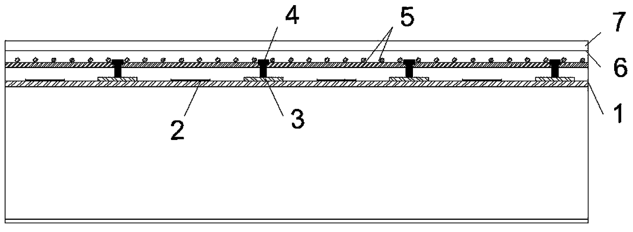
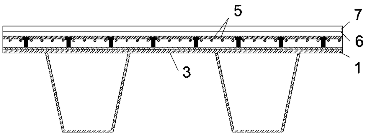
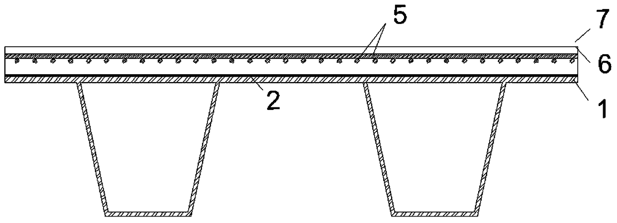
[0033] Example 1, the present invention includes a cracked steel bridge deck, carbon fiber reinforced slats, metal reinforced slats, shear connectors, steel mesh, ultra-high performance concrete layers and wear layers, and the carbon fiber reinforced slats are passed through an organic structural adhesive Bonded on the cracked steel panel, the metal reinforced strips are welded with shear connectors, and the metal reinforced strips with shear connectors can be directly welded or glued on the cracked steel bridge deck, and connected with the The carbon fiber reinforced slats are arranged in parallel and alternately. The steel mesh is placed on the cracked steel bridge deck. The steel mesh is composed of criss-cross longitudinal steel bars and transverse steel bars. panel, and covered with carbon fiber reinforced slats, metal reinforced slats, shear connectors, steel mesh and cracked steel bridge deck, the wear layer is covered on the top surface of the ultra-high performance con...
Embodiment 2
[0034] Embodiment 2, the shear connector of the present invention comprises stud, T-shaped steel, L-shaped steel, channel steel, PBL perforated steel plate connector, refer to Figure 1 to Figure 3 , and the rest are the same as the combination of any of the above embodiments or two or more embodiments.
Embodiment 3
[0035] Embodiment 3, the steel bar connector of the present invention comprises a bent steel bar connector, see Figure 1 to Figure 3 , and the rest are the same as the combination of any of the above embodiments or two or more embodiments.
PUM
| Property | Measurement | Unit |
|---|---|---|
| Compressive strength | aaaaa | aaaaa |
| Compressive strength | aaaaa | aaaaa |
Abstract
Description
Claims
Application Information