Laser radar emitting system based on MEMS galvanometer

A laser radar and transmitting system technology, applied in radio wave measurement systems, instruments, etc., can solve the problems affecting the popularity of laser radar, high precision requirements for components, and high module manufacturing costs, to improve accuracy and to achieve consistency and resolution. The effect of improving efficiency and avoiding cost increase

Inactive Publication Date: 2019-02-15
CHINA ELECTRONIC TECH GRP CORP NO 38 RES INST
View PDF11 Cites 24 Cited by
  • Summary
  • Abstract
  • Description
  • Claims
  • Application Information

AI Technical Summary

Problems solved by technology

[0003] However, in order to ensure the high resolution of space scanning in the existing laser radar, most of the transmitting modules of the laser radar are complex and precise optical path adjustment mechanisms. Affect the popularity of lidar and restrict the development of robots and unmanned driving

Method used


Image

  • Laser radar emitting system based on MEMS galvanometer
  • Laser radar emitting system based on MEMS galvanometer
  • Laser radar emitting system based on MEMS galvanometer

Examples


Embodiment 1

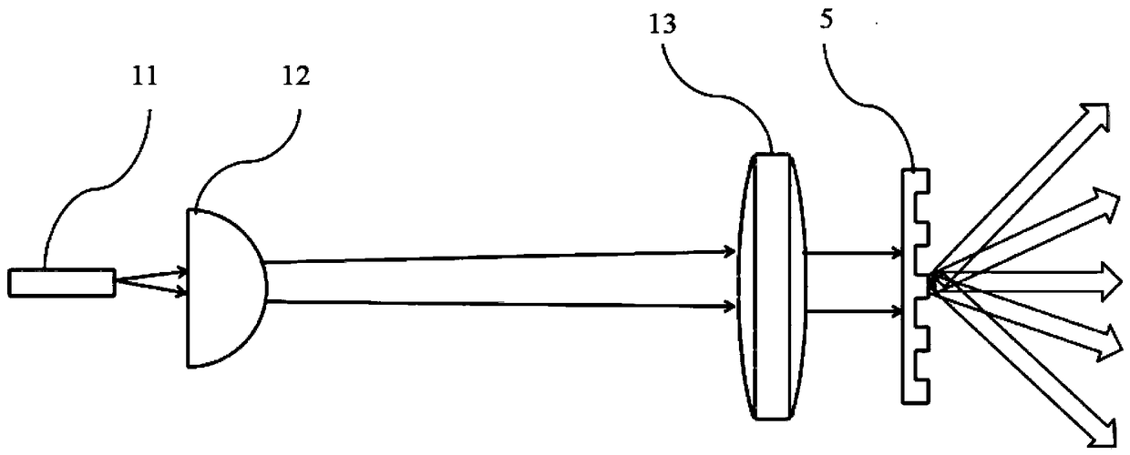
[0027] The lidar transmitting system in this embodiment includes a pulsed laser collimating transmitting module 1 and a diffractive beam splitting element 5; the pulsed laser collimating transmitting module 1 and the diffractive beam splitting element 5 are arranged correspondingly.

[0028] The pulsed laser collimation emission module 1 includes a laser 11, and the pulse laser collimation emission module 1 realizes the collimation processing of the light source of the laser 11 through a combination of optical systems, and the collimated laser after collimation is vertically incident into the On the diffractive beam splitting element 5, the diffractive beam splitting element 5 divides the vertically incident collimated laser evenly into several divergent beams, and the angle between the divergent beams can be adjusted by adjusting the diffractive beam splitting element 5 structure for precise control.

[0029] The laser radar transmitting system is also provided with a rotatin...

Embodiment 2

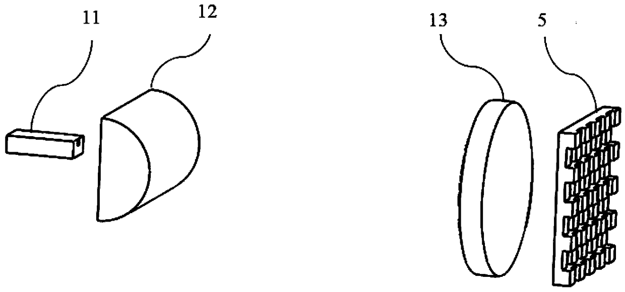
[0032] like figure 1 as shown, figure 1 It is a structural perspective view of Embodiment 2 of the lidar transmitting system; the pulsed laser collimating transmitting module 1 also includes a cylindrical lens 12 and an aspheric lens 13, and the cylindrical lens 12 and the aspheric lens 13 are arranged on the Between the laser 11 and the diffraction beam splitting element 5, the laser 11 is preferably a pulsed semiconductor laser; the diffraction beam splitting element 5 is preferably a diffraction grating beam splitting element.

[0033] Specifically, the size of the light emitting surface of the semiconductor laser 11 in the direction of the fast axis and the direction of the slow axis is quite different. Generally, the divergence angle of the laser light emitted by the laser 11 in the direction of the fast axis is relatively large.

[0034] Therefore, the present invention first compresses the divergence angle of the laser light emitted by the laser 11 in the direction of ...

Embodiment 3

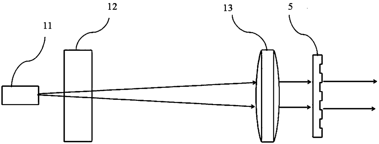
[0040] Embodiment 3 is further improved on the basis of Embodiment 1. The improvement is that the lidar transmitting system further includes a mirror 3 and a rotating motor 4 .

[0041] like Figure 4 , Figure 5 as shown, Figure 4 It is a three-dimensional structure diagram of the third embodiment of the lidar transmitting system; Figure 5 It is a structural top view of Embodiment 3 of the laser radar transmitting system; the mirror 3 is connected to the rotating motor 4, and the rotating motor 4 can drive the mirror 3 to rotate so as to adjust the distance between the laser and the mirror 3 The included angle changes the incident angle and reflection angle of the laser light incident on the reflector 3 .

[0042] The reflector 3 is arranged between the pulse laser collimation emission module 1 and the diffraction beam splitting element 5; the pulse laser collimation emission module 1, the diffraction beam splitting element 5, the reflection mirror 3 and the rotary motor ...


PUM


Abstract

The invention discloses a laser radar emitting system based on a MEMS galvanometer. The system comprises a pulsed laser collimation emission module, a MEMS galvanometer, a reflecting mirror, a rotarymotor, and a diffraction beam splitting element. The pulsed laser collimation emission module emits collimated laser; the MEMS galvanometer, the pulsed laser collimation emission module, the reflecting mirror, and the diffraction beam splitting element are arranged correspondingly, so that the collimated laser incidents on the surface of the MEMS galvanometer to be reflected to form reflected light; the reflected light incidents on the reflecting mirror, and is reflected by the reflecting mirror to further incident on the diffraction beam splitting element, so that a quantity of uniform divergent light beams are formed; the reflecting mirror is connected to the rotary motor; and the rotary motor can drive the reflecting mirror to rotate. According to the laser radar emitting system based on the MEMS galvanometer, the rotation angle of the rotary motor is adjusted for multiple rounds of scanning; and the spatial range of angles between adjacent beams under a single scan can be filled, thereby greatly improving the spatial scanning resolution.

Description

technical field [0001] The invention relates to the technical field of laser radar, in particular to a laser radar transmitting system based on a MEMS vibrating mirror. Background technique [0002] In recent years, with the vigorous development of robotics and unmanned driving, the demand for intelligent perception sensors has become more and more urgent. Lidar is one of the key core intelligent perception sensors. It has the advantages of high ranging accuracy, strong directionality, fast response, and is not affected by ground clutter, and can effectively provide the information required by robots and vehicle decision-making and control systems. At present, the most effective solution for environmental sensing such as robots and unmanned driving. [0003] However, in order to ensure the high resolution of space scanning in the existing laser radar, most of the transmitting modules of the laser radar are complex and precise optical path adjustment mechanisms. It affects ...

Claims


Application Information

Patent Timeline
Patent Type & Authority Applications(China)
IPC IPC(8): G01S7/484G01S7/481
CPCG01S7/4814G01S7/484
Inventor 金里陈丛杨孝东曹国威李由程国云刘剑辉郭进
Owner CHINA ELECTRONIC TECH GRP CORP NO 38 RES INST
Why Eureka
Try Eureka