Under-sampling phase detection method and device used in phase laser range finding

A laser ranging and undersampling technology is applied in the phase detection field of phase laser ranging, which can solve the problems of noise, high frequency of signals and echo signals, and it is difficult to accurately extract phase information, etc., so as to improve the accuracy and frequency. Resolution, the effect of reducing the amount of calculation

Inactive Publication Date: 2019-02-15
HARBIN UNIV OF SCI & TECH
View PDF2 Cites 2 Cited by
  • Summary
  • Abstract
  • Description
  • Claims
  • Application Information

AI Technical Summary

Problems solved by technology

[0007] The purpose of the present invention is to solve the problem that it is difficult to accurately extract the phase information by using the existing phase detection method due to the high frequency of the transmitted signal and the echo signal in the phase type laser range finder. Under-sampling phase detection method and device

Method used


Image

  • Under-sampling phase detection method and device used in phase laser range finding
  • Under-sampling phase detection method and device used in phase laser range finding
  • Under-sampling phase detection method and device used in phase laser range finding

Examples


specific Embodiment approach 1

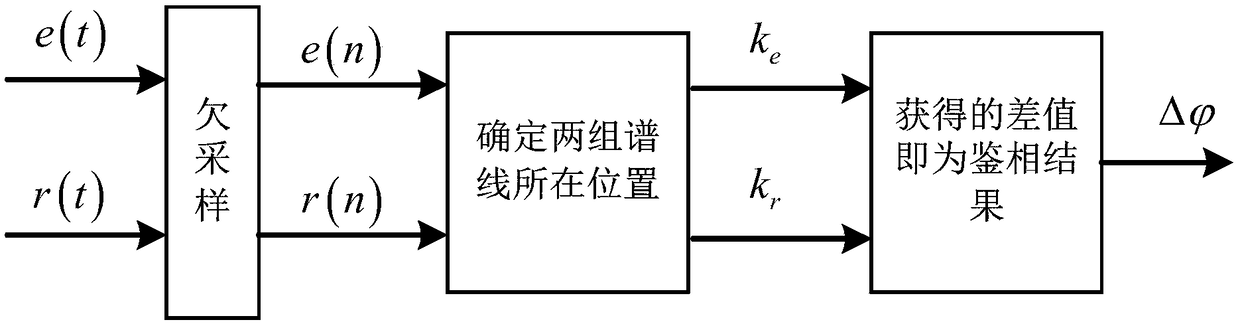
[0026] Specific implementation mode one: refer to figure 1 , 2 and 3 specifically illustrate the present embodiment, a kind of subsampling phase identification method for phase type laser ranging described in the present embodiment, the method comprises the following steps:

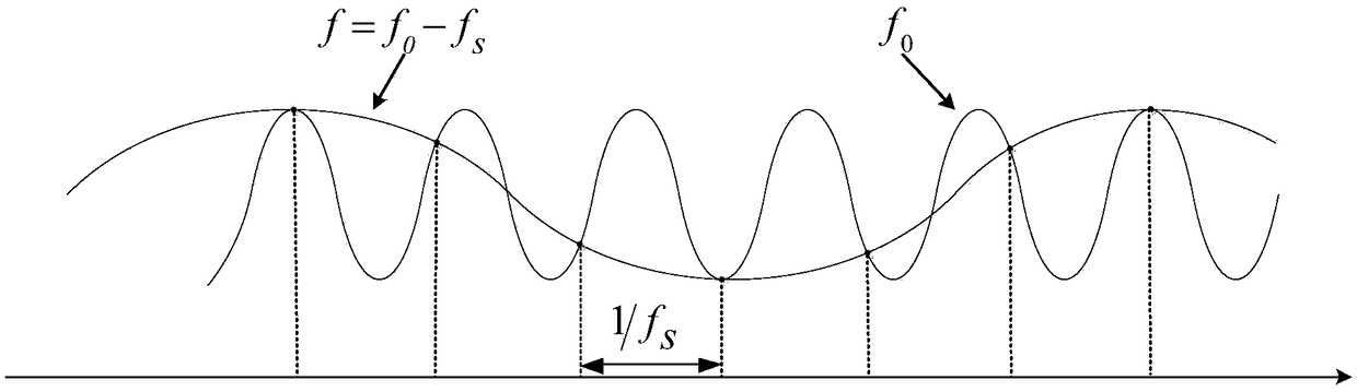
[0027] Step 1: Set the undersampling frequency f s The transmitted signal e(t) and the echo signal r(t) are under-sampled. Since e(t) and r(t) contain noise, in practice, the under-sampling frequency f s Need to meet: 0.5f s 0 s , 2f 0 / f s ≠ integer.

[0028] The expression of the transmitted signal e(t) is:

[0029]

[0030] The expression of the echo signal r(t) is:

[0031]

[0032] In the above formula, A 1 and B 1 are the magnitudes of e(t) and r(t), respectively, with are the initial phases of e(t) and r(t), respectively, f 0 is the modulation frequency, and t is the time.

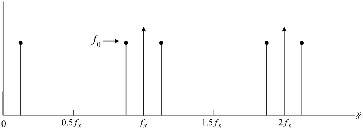
[0033] After the undersampling operation, the spectra of e(t) and r(t) lie in the spectral band [f s / 2...

specific Embodiment approach 2

[0064] Specific implementation mode two: refer to Figure 4 with 5 Describe this embodiment in detail, a kind of subsampling phase detection device for phase type laser ranging described in this embodiment,

[0065] The under-sampling phase detection device adopts the "FPGA+ARM" method, and the FPGA is used for signal acquisition and processing, and the ARM processor realizes the control of the system, and the phase detection results are transmitted to the host computer in real time through the network interface circuit. Described sampling phase discrimination device specifically comprises: program-controlled amplifying circuit 1, analog-to-digital conversion circuit (ADC) 2, FPGA3, ARM control unit 4, trigger circuit 5, network interface circuit 6 and upper computer 7;

[0066] The program-controlled amplifying circuit 1 is used to collect transmission signals and echo signals, and amplify the collected signals. The waveform signal output terminal of the program-controlled a...


PUM


Abstract

An under-sampling phase detection method and device used in phase laser range finding relate to the field of phase laser range finding. The invention aims to solve the problem that it is difficult toaccurately extract phase information by using the existing phase detection method because of the high frequency and noise of the transmitted signals and the echo signals in the phase laser rangefinder. The method of the invention includes the following steps: transmitted signals and echo signals are under-sampled, and a discrete sequence of the transmitted signals and a discrete sequence of the echo signals are obtained; discrete Fourier transformation is carried out on the two discrete sequences, the maximum values of spectral lines in the two discrete sequences are selected according to theresult of transformation, and the locations of the two groups of spectral lines are determined according to the maximum values of the two groups of spectral lines; and the initial phases of the transmitted signals and the echo signals are calculated according to the locations of the two groups of spectral lines, difference operation is performed on the initial phases of the transmitted signals andthe echo signals, and the difference obtained is the phase detection result. The method and the device are used to extract the phase information of high-frequency signals in a phase laser rangefinder.

Description

technical field [0001] The invention belongs to the field of phase type laser ranging, in particular to phase identification of phase type laser ranging. Background technique [0002] At present, phase identification methods can be generally divided into two categories: traditional phase identification methods and phase identification methods based on digital processing. [0003] Traditional phase detection methods mainly include analog phase detection method and digital phase detection method, which are characterized by processing in the time domain and are easily affected by noise. The analog phase detection method refers to the measurement of the signal phase through an analog circuit. This method has high requirements on the performance of analog devices, and the implementation of the circuit is complicated, which is not conducive to integration. The digital phase detection method counts the time interval between the reference signal and the measurement signal through a...

Claims


Application Information

Patent Timeline
Patent Type & Authority Applications(China)
IPC IPC(8): G01S17/36
CPCG01S17/36
Inventor 盖建新滕晓刘海龙
Owner HARBIN UNIV OF SCI & TECH
Why Eureka
Try Eureka