Flange structure transducer with vibration isolation function for ultrasonic device

A transducer and ultrasonic technology, which is applied in the field of ultrasonic tool holders and flange structure transducers, can solve the problems of ultrasonic vibration energy loss, affecting the rotation of the machine tool spindle, and low efficiency of ultrasonic processing, so as to reduce losses and avoid machine tools. Spindle damage, the effect of improving the efficiency of ultrasonic machining

Pending Publication Date: 2019-02-19
CONPROFE TECH GRP CO LTD +1
View PDF7 Cites 3 Cited by
  • Summary
  • Abstract
  • Description
  • Claims
  • Application Information

AI Technical Summary

Problems solved by technology

[0003] In the prior art, when the transducer is connected to the body of the ultrasonic device in the ultrasonic device, a large part of the ultrasonic vibration will be transmitted to the body of the ultrasonic device, resulting in the loss of ultrasonic vibration energy, and the efficiency of ultrasonic processing is low; in addition, when replacing When the transducer is used in an ultrasonic tool holder, the transducer is connected to the tool holder body, and part of the ultrasonic vibration is transmitted through the tool holder body to the machine tool spindle connected to its rear end, which will not only affect the rotation of the machine tool spindle, but also produce damage to the machine tool spindle. The impact can even cause damage to the machine tool

Method used


Image

  • Flange structure transducer with vibration isolation function for ultrasonic device
  • Flange structure transducer with vibration isolation function for ultrasonic device
  • Flange structure transducer with vibration isolation function for ultrasonic device

Examples


Embodiment 1

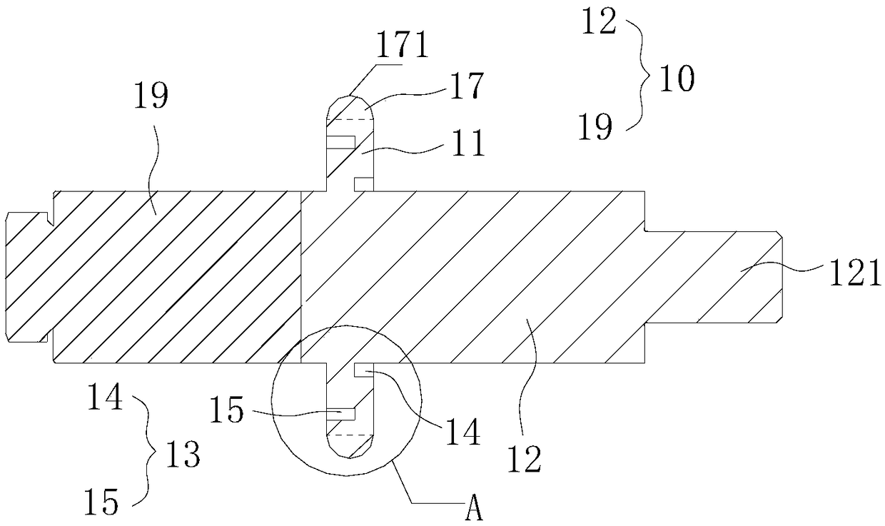
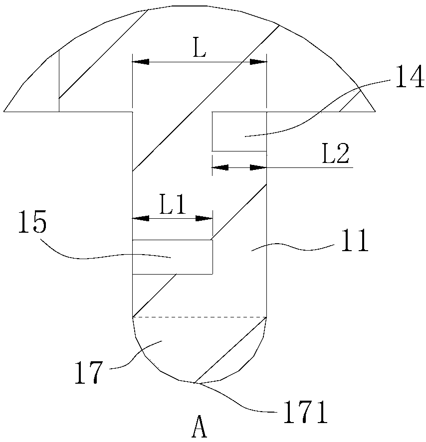
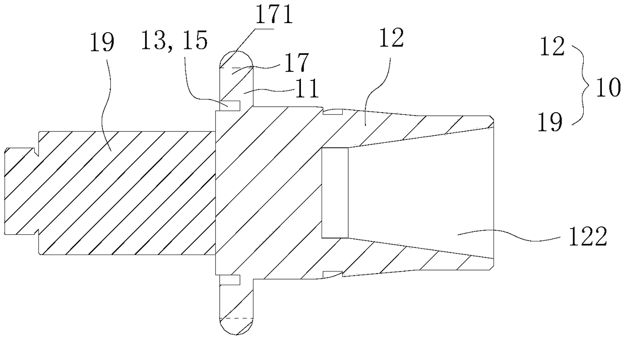
[0094] The present invention proposes a flange structure transducer 1 with vibration isolation function for ultrasonic devices. For the transducer in this embodiment, please refer to the appended figure 1 , 1a , 1b, and 1c, the transducer 1 includes a transducer body 10 and a flange 11 disposed on the periphery of the transducer body 10, the front end of the transducer body 10 is used to install the processing tool 5, and the flange 11 A vibration-damping structure 13 for reducing the transmission of ultrasonic vibrations from the transducer 1 to the body of the ultrasonic device is provided on the top; the vibration-damping structure 13 includes a protrusion integrally formed on the outer edge of the flange 11 and used to connect with the body of the ultrasonic device 17 , the protruding portion 17 protrudes outward along the radial direction of the flange 11 .

[0095] As shown in Table 1, based on the above-mentioned technical scheme, the connection form between the flange...

Embodiment 2

[0113] Please refer to the attached figure 2 , 2a , 2b, 2c, and 2d, this embodiment proposes a transducer 1 for an ultrasonic device, the difference from Embodiment 1 is that in this embodiment, the raised portion 17 includes several flanges 11 The protruding blocks 172 are arranged at intervals in the circumferential direction on the outer edge of the outer edge, and several protruding blocks 172 are surrounded into a ring shape surrounding the transducer body 10 . Further, an arc-shaped groove 16 is provided between two adjacent protrusions. Furthermore, the top of the bump 172 is a plane, and the top of the plane is the largest outer diameter of the flange, which is the welding position 171 for welding with the ultrasonic device body, and the welding position 171 is the position of the vibration zero point. During the transducer 1 and the ultrasonic device body, the connection position of the flange 11 and the ultrasonic device body is thus arranged at the position of th...

Embodiment 3

[0119] Please refer to the attached image 3 , 3a , 3b, 3c, and 3d, this embodiment proposes a transducer for an ultrasonic device, and its difference from Embodiment 1 is only that the raised portion 17 of this embodiment is a ring around the transducer body 10 ring shape; further, the outer diameter of the raised portion 17 gradually decreases from the middle to its two ends and forms a semicircular arc when viewed along the axial section of the transducer body 10, specifically refer to the attached Figure 3c As shown; the first damping groove structure 14 of this embodiment includes a first annular groove 141 centered on the center of the front end face of the flange 11; the second damping groove structure 15 includes the flange The center of the rear end face of 11 is the second annular groove 151 that the circle center offers; Figure 3c As shown, the first annular groove 141 and the second annular groove 151 are arranged in an offset manner, and the sum of the depths ...


PUM


Abstract

The invention discloses a flange structure transducer with a vibration isolation function for an ultrasonic device. A damping structure is arranged on a flange of the transducer, and comprises a protruding part which is integrally formed on the outer edge of the flange and used for being connected with an ultrasonic device body. The protruding part protrudes outwards in the radial direction of theprotruding flange, and the connecting form of the flange and the ultrasonic device body can be changed through the protruding part. The protruding part and the ultrasonic device body are connected, and therefore the connecting area of the flange and the ultrasonic device body can be reduced to reduce ultrasonic vibration transmission between the transducer and the ultrasonic device body, and thenloss of ultrasonic vibration energy is reduced, and it is ensured that ultrasonic vibration energy is effectively transmitted to a processing tool to improve the ultrasonic processing efficiency of the processing tool. When the transducer is used for an ultrasonic cutter handle, ultrasonic vibration transmitted to a machine tool spindle can be reduced, and the ultrasonic vibration is prevented from influencing rotation of the machine tool spindle and damaging the machine tool spindle.

Description

technical field [0001] The invention relates to the technical field of ultrasonic processing, in particular to a flange structure transducer with vibration isolation function used in an ultrasonic device and an ultrasonic tool handle including the transducer. Background technique [0002] The transducer is the key mechanism that provides ultrasonic vibration energy in the ultrasonic device. Its working principle is to use the piezoelectric effect or magnetostrictive effect to convert the frequency electrical signal into high-frequency ultrasonic vibration, and transmit the ultrasonic vibration energy to the processing tool for further processing. Process the workpiece. Among them, the processing tools can be cutting tools, grinding heads, etc., and the transducers are mainly used in ultrasonic devices such as ultrasonic tool handles, ultrasonic fixtures, ultrasonic spindles, and ultrasonic machine tools. [0003] In the prior art, when the transducer is connected to the bod...

Claims


Application Information

Patent Timeline
IPC IPC(8): B06B3/00
CPCB06B3/00
Inventor 李伟秋颜炳姜
Owner CONPROFE TECH GRP CO LTD
Why Eureka
Try Eureka