
Carbon fiber processing and production sealing device

A sealing device and carbon fiber technology, which is applied to the chemical characteristics of fibers, textiles and papermaking, etc., can solve the problems of increased polluted fibers, decreased carbon fiber quality, and large exhaust resistance, so as to prevent polluted fibers, increase carbon content, and reduce resistance. small effect

Inactive Publication Date: 2019-02-19
浙江虹腾新材料有限公司
View PDF5 Cites 0 Cited by
  • Summary
  • Abstract
  • Description
  • Claims
  • Application Information

AI Technical Summary

Problems solved by technology

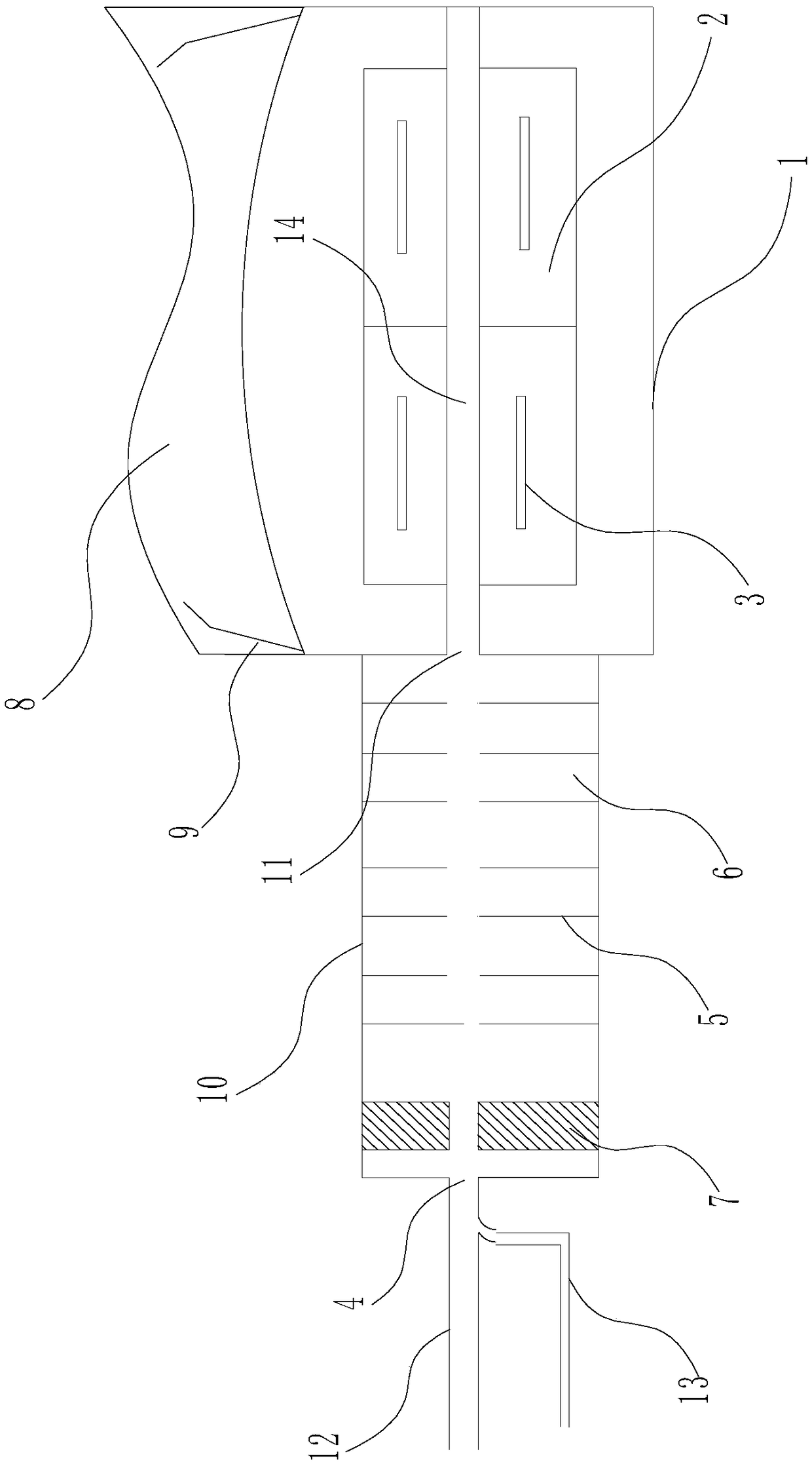
[0002] The sealing device is an essential device for the carbonization furnace. The sealing effect directly affects the quality of the carbon fiber carbonization furnace, and the phenomenon of narrowing and widening will inevitably occur, followed by wool and disorder (referring to the relative position of the tow running ), leading to the decline in the quality of carbon fiber and the instability of production. At present, some domestic units cannot produce qualified carbon fiber due to the reduction and expansion of the width, and are forced to stop production. , low-temperature carbonization, high-temperature carbonization, surface treatment and sizing process, the furnace mouth and channel are the same width, no shrinkage, no expansion, once through to the end, the tow runs smoothly. To realize the "big channel" production line, it must be equipped with high-efficiency Labyrinth sealing device to ensure the positive pressure operation of the carbonization process. The position of the exhaust gas outlet can be on the top or side of the furnace body. On the top, the exhaust is smooth and the resistance is small, but the probability of tar dripping to pollute the fiber is greatly increased; the side exhausts the exhaust gas and has a The tar tank can avoid the dripping of tar, but the exhaust resistance is large and the exhaust is not smooth. Therefore, it is necessary to redesign a sealing device used in conjunction with the carbonization furnace to achieve smooth exhaust and prevent tar from polluting the fiber seal. device

Method used


Image

  • Carbon fiber processing and production sealing device

Examples


Embodiment Construction

[0022] In order to make the technical means, creative features, goals and effects achieved by the present invention easy to understand, the present invention will be further elaborated below in conjunction with illustrations and specific embodiments.

[0023] refer to figure 1 As shown, the sealing device used for carbon fiber processing and production has a main body of a sealing body 10, which is composed of a baffle 5, an expansion chamber 6 and a gas ejection part 7, and the baffle 5 is installed in the expansion chamber 6, the gas ejection part 7 is installed on one side of the sealing body 10, the expansion chamber 6 is provided with a plurality, and the plurality of expansion chambers 6 are connected to each other, and the plurality of expansion chambers 6 are connected by a resistance Flow plate 5 separates;

[0024] A plurality of said expansion chambers 6 are separated and formed by baffles 5;

[0025] The baffles 5 are parallel to each other, and the center of the...


PUM


Abstract

Disclosed is a carbon fiber processing and production sealing device. The carbon fiber processing and production sealing device comprises a sealing body, which is composed of spoilers, expansion chambers and a gas ejecting unit, wherein the spoilers are arranged inside the expansion chambers, the gas ejecting unit is arranged on one side of the sealing body, and the expansion chambers are connected into a whole and separated through the spoilers; inert gas passes through a gas flow distributing plate composed of porous plates of the gas ejecting unit and then into the expansion chamber to protect raw fiber inside the expansion chamber from oxidation and to improve the carbon content of the raw fiber; an exhaust device is mounted at the upper end of the arc surface of a carbonization furnace, the cross section of the carbonization furnace is in an arc shape, which can avoid deformation at high temperature and meanwhile guide dropping tar to flow to both sides to avoid contaminating thefiber.

Description

technical field [0001] The invention relates to the technical field of carbon fiber processing and production, in particular to a sealing device for carbon fiber processing and production. Background technique [0002] The sealing device is an essential device for the carbonization furnace. The sealing effect directly affects the quality of the carbon fiber carbonization furnace, and the phenomenon of narrowing and widening will inevitably occur, followed by wool and disorder (referring to the relative position of the tow running ), leading to the decline in the quality of carbon fiber and the instability of production. At present, some domestic units cannot produce qualified carbon fiber due to the reduction and expansion of the width, and are forced to stop production. , low-temperature carbonization, high-temperature carbonization, surface treatment and sizing process, the furnace mouth and channel are the same width, no shrinkage, no expansion, once through to the end, t...

Claims


Application Information

Patent Timeline
IPC IPC(8): D01F9/12
CPCD01F9/12
Inventor 鲍泉华
Owner 浙江虹腾新材料有限公司
Learn More